Rough Country 674X User Manual
Page 4
FRONT INSTALLATION INSTRUCTIONS
1. Prior to installing this kit, with the vehicle on the ground, measure the heights of your vehicle. This measurement can
be recorded from the center of the wheel straight up to the top of the inner fender lip. Record the measurements.
LF:__________ ,RF:___________,
LR:__________, RR:___________
2. Place vehicle in park and chock the rear wheels. Raise the front of the vehicle with a jack and secure a jack stand
beneath each frame rail behind the front control arms. Ease the frame down onto the stands.
3. Remove the front tires/wheels
,
using a 19mm deep well socket.
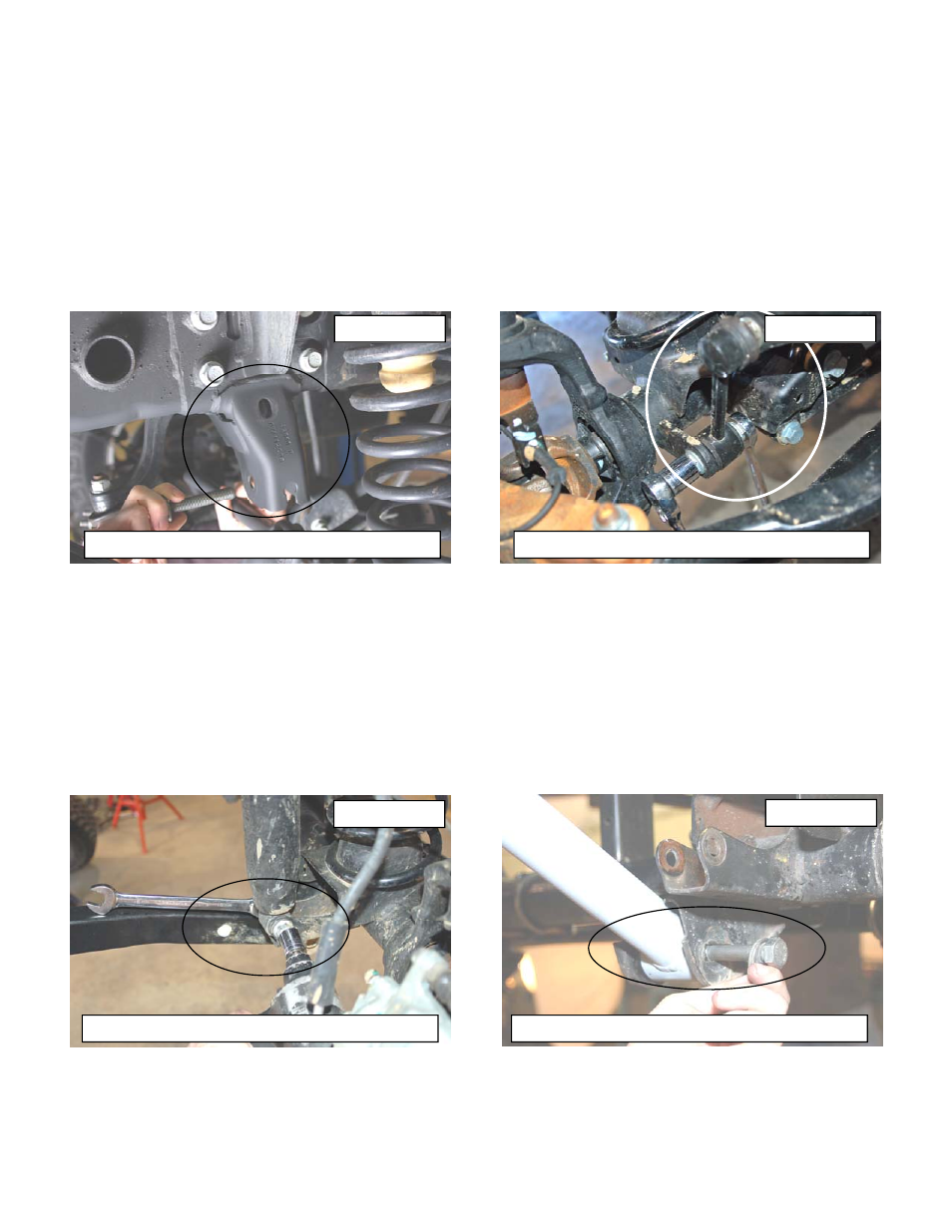
4. Using a 21mm socket, remove bolt securing the front track bar to the frame. Retain stock hardware. See Photo 1.
5. Using a 18mm socket and wrench remove the bottom sway bar bolts. Using a 19mm socket and 18mm wrench, re-
move the top of the sway bar link. Retain hardware for later use. See Photo 2.
6. Remove the lower shock bolt using a 18mm socket and wrench. Using a 5/8” wrench unbolt the top of the shock and
remove. See Photo 3. Retain the lower stock hardware.
7. Using a 21mm socket and wrench loosen the lower control arm bolts and a 18mm for the upper arms at the axle and
frame, but do not remove.
8. On some models it will be necessary to remove the brake line bracket from the frame to allow the coils to be re-
moved. Using a 10MM socket, remove the brake line bracket from the stock location.
9. Push down on the axle to allow room for the coils to be removed. Remove stock coil springs. Retain coil isolators.
10. Using a 21mm wrench, remove the bolts that secure the lower link arms to the axle.
11. Assemble the lower control arms with the adjustable end & adjust the arm to a length of 22 7/8” from center of hole
to center of hole and tighten the jam nut using a 1 7/8” wrench. Install the adjustable end in the frame mount and the
other end in the axle mount. Do not tighten arms in the mounts at this time. See Photo 4. The bend on the lower
control arm should be facing inward to allow for the tires to achieve full lock to lock turning.
PHOTO 3
PHOTO 1
PHOTO 2
PHOTO 4
Remove the track rod from the frame
Remove the front sway bar links
Remove the front shock absorbers
Install new lower control arms