Rough Country 372.20 User Manual
Page 2
9. Attach the grease fittings provided with the new Rough Country lower suspension arms using a 3/8" wrench. Note:
install two 90º grease fittings into the lower suspension arms. Insert the two bushing halves into the lower suspen-
sion arm and press in the lower suspension arm sleeve provided. The 2000 and above will use the qty 4-short
14mm sleeves for the upper arm and the lower arm will use the qty 4-16mm longer sleeves. The installer can
check this by using the stock arm bolt. The use of a vice or C-clamp may facilitate the insertion of the sleeve.
10. Install the new Rough Country lower suspension arms in place of the stock lower suspension arms as shown in
Photo 5. Slight prying of the mounts may be necessary for arm installation. Install the original rear suspension arm
bolt and slightly tighten the nut. Install the original front suspension arm bolt and slightly tighten the nut. Refer to the
reference mark on the cam bolt and the axle when installing the cam bolt.
FRONT INSTALLTION INSTRUCTIONS
1. Block the rear wheels of the vehicle. Raise the front of the vehicle and support the vehicle with jack stands under the
frame rails. Remove the front wheels and tires and set aside. Position a hydraulic jack under the front axle and raise
the jack until the front suspension begins to compress
.
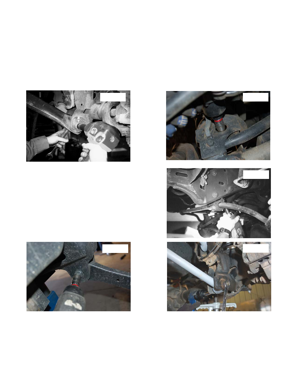
2. On both sides of the vehicle, scribe alignment marks on the adjustment cam and axle bracket at the lower link to
axle attachment point for later reference. See Photo 1
3. Unbolt the brake line brackets from the axle to ensure brake line free play during the suspension system installation.
Remove the center disconnect vacuum lines from the clamp on the axle.
4. Remove the nut, retaining washer and rubber bushing from the both upper shock mounts located inside the engine
compartment.
5. Remove the lower shock bolts on the axle as shown in Photo 2 and save for later installation. The shock absorbers
will be removed from the vehicle at the same time the coils are removed from the vehicle.
6. Remove the (4) bolts on the sway bar to frame brackets and al-
low the sway bar to rotate down. Save these bolts for later in-
stallation.
See Photo 3.
7. Carefully lower the jack until the coil springs are free (the upper
suspension arm will be contacting the axle bracket) Remove the
coil springs and shocks from the vehicle. Note: use of a coil
spring compressor may be required for spring removal.
8. Remove the lower suspension arm nut, cam and cam bolt from
the axle. Remove the nut and bolt from the frame attachment
point as shown in Photo 4 and remove the lower suspension
arm from the vehicle. Repeat this step for the opposite side of
the vehicle. Note: save bolts, nuts and washers for later installa-
tion.
Photo 1
Photo 2
Photo 4
Photo 3
Photo 5