Rough Country 525.20 User Manual
Page 3
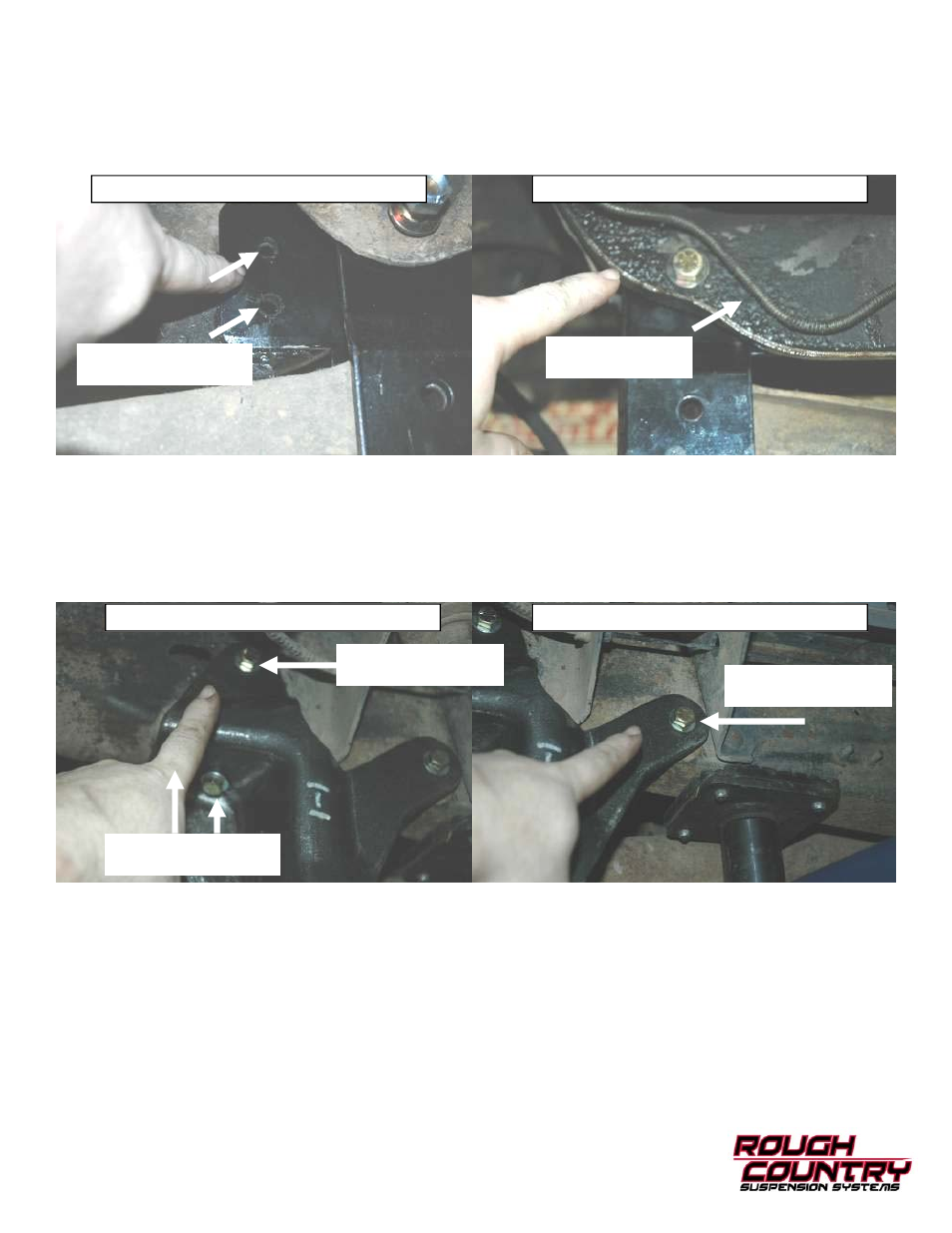
12. Detach the pivot bracket from the passengers side cross member. Using 21mm socket and 22mm wrench install the
new axle pivot bracket for the passengers side. Attach bracket to cross member with furnished 9/16” x 1” bolt, wash-
ers, and locknuts. Torque to 100 ft. lbs. IMPORTANT Be sure that the axle pivots are vertically aligned. Drill two
7/16” holes through the cross member and the new bracket. Using a 16mm socket, and a 17mm wrench install the
7/16” bolts, washers, and lock nuts. Reinstall the stock axle bolt through the appropriate hole 4” for the top hole, and
6” for the bottom hole. Torque to 60-75 ft. lbs.
13. Using a 16mm socket, and a 17mm wrench, the new radius arm lowering brackets are installed with furnished 7/16"
bolts, locknuts and flat washers. The factory nylon radius arm bushing rings, mounted directly against the rear face
of the stock stamped steel radius arm brackets, are not reused. The replacement brackets design allows you to dis-
card these pieces that are prone to fail. On 1980 and some 1981 models, all but one bracket-to-frame hole must be
drilled. Match the rear hole of the new bracket to the rear frame hole on the bottom of rail. Drill all other holes. Be
wary of wiring/hoses routed inside of the frame rails. Inspect radius arm bushings for cracks, dry rot and deformities.
Torque radius arm bushing nuts to 80-100 ft. lbs.
14. Install new coil spring. When lowering the axles for spring installation, take care not to overextend the factory rubber
brake hoses. Using a 13mm socket reinstall the spring clip and torque to 13-18 ft. lbs. Using a 1 1/8” wrench reinstall
lower nut and torque to 50-70 ft. lbs. On some vehicles factory equipped with dual front shocks, keep the bottom of
the coil pulled as far rearward as possible to gain clearance between coil and front shock.
15. Repeat procedure on passenger side
16. Install Pitman Arm per their separate instructions. Attach drag link to pitman arm nut and install cotter pin.
17. On vehicles factory equipped with front anti-sway bar, install relocating hardware (purchased separately, see SEPA-
RATE INSTRUCTIONS). This is also a good opportunity to replace worn factory rubber bushings.
18. Reinstall wheels and tires.
19. Remove jack stands and lower vehicle to the ground. If vehicle is equipped with a front sway bar, relocation brackets
are required if you are installing a 6” lift. Install these now per separate instructions.
20. Check all fasteners to be sure they are torqued properly.
21. Install warning to driver sticker on sun visor.
Drill 7/16” Holes Here
For Bracket Installation
Passenger Side Axle Bracket— View From Rear
Passenger Side Axle Bracket—View From Front
When Drilling Show
Care to Miss Line
Radius Arm Bracket Installation
Radius Arm Bracket Installation
Using these factory
holes to secure bracket
Drill 7/16” Hole Here
For Bracket Installation
Drill 7/16” Hole Here
For Bracket Installation