Rough Country 525.20 User Manual
Page 2
INSTALLATION INSTRUCTIONS
1. Place the vehicle on a level surface. Set the parking brake. Center front wheels and chock rear wheels. Place a floor
jack under the outer ends of both axle halves and evenly raise vehicle approximately 12". Place jack stands under
frame rails approximately 4" behind radius arm brackets. Ease vehicle down onto stands. Continue down with jacks
until there is only a slight load on the coil springs.
2. If vehicle is equipped with anti-sway bar, disconnect drop-links at the attaching points. Bar relocation is performed in
a later step and with separate instructions in kit #1018. (6” lifts must have a sway bar drop down bracket kit.)
3. Remove front tires and wheels.
4. Using a 14 mm wrench remove the nut from the top of the factory shock. Using a 19mm socket and wrench If longer
brake hoses are being used, disconnect the stock rubber hoses where they connect to the metal lines at the frame
rails. A piece of rubber tubing routed from the metal lines to a catch pan will eliminate a fluid mess. New hoses are
installed in a later step. If the stock rubber units are retained, they must be in good condition; check for chafed spots,
cracks and dry rot.
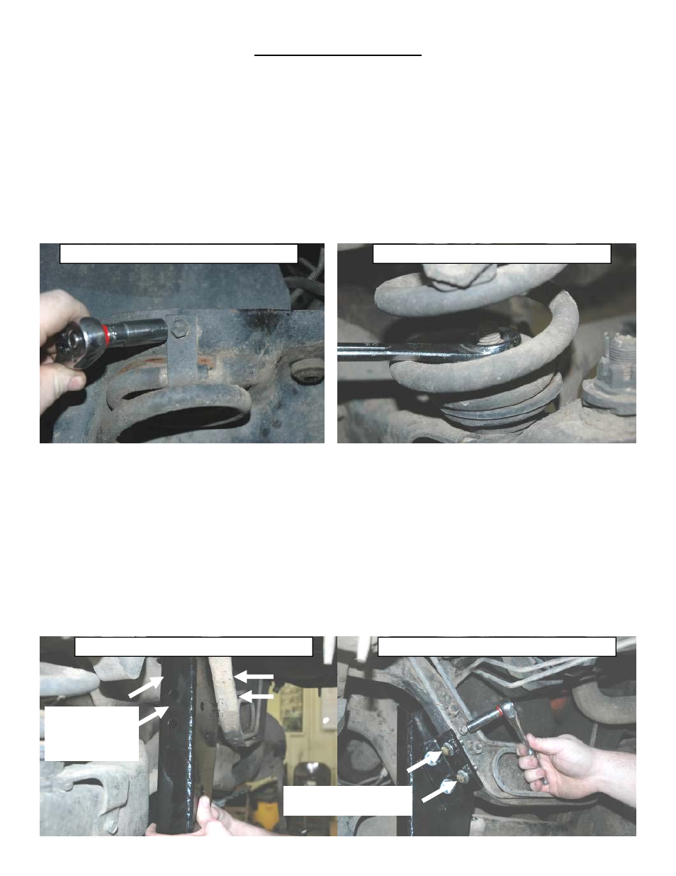
5. Using a 13mm wrench remove the coil clip from the top of the coil seat. Retain clip and hardware for later use.
6. Using a 1 1/8” wrench remove the nut on the lower coil seat. Retain nut for later use.
7. Install a coil spring compressor on the coil and compress enough to remove the coil spring.
8. Using a 1 1/8” wrench remove the nut from the end of the radius arm and remove stock bushings. Retain the hard-
ware for later use.
9. Some Ford trucks come from the factory with the radius arms, and I-beam brackets riveted on. If your truck has riv-
ets you can use an air hammer, or torch to remove the rivets. If a torch is used to remove the rivets, take care not to
damage any wiring/hoses routed inside the frame rails. Supporting I beam, remove the radius arm drop brackets
from the vehicle, and discard.
10. Remove both axle eye pivot bolts. Detach the pivot bracket for the driver’s side axle cross member.
11. Loosely attach the axle pivot bracket for the driver’s side axle using the supplied mounting hardware. Bolt up to the 4
existing holes before tightening. Using a 16mm socket and a 17mm wrench torque to 60-75 ft. lbs. Attach the side
support bracket with the supplied 7/16” bolts and hardware so it firmly against frame flange. Drill two 7/16” holes at
existing holes in bracket, through the cross member lip. Install furnished 7/16” bolts, and locking nuts, flat washers
are not required. Reinstall stock axle bolt through appropriate hole, 4” top hole, 6” bottom hole. Torque bolts to 60-
75ft. lbs.
Remove Upper Coil Clip
Remove Nut on Lower Coil Seat
Driver Side Axle Bracket
Driver Side Axle Bracket Support
Drill Holes Here For Sup-
port Bracket Installation
Bolt up into exist-
ing 4 holes—don’t
tighten until all 4
bolts are in place.