Rough Country 663U User Manual
Page 6
31. Locate the front lower control arm bushings and lubricate them with a lithium grease. Assemble the bushings and
sleeves in the lower control arm. Adjust the arm to a length of 29 3/4” from center of bushing to center of bush-
ing. Tighten jam nut using an adjustable wrench.
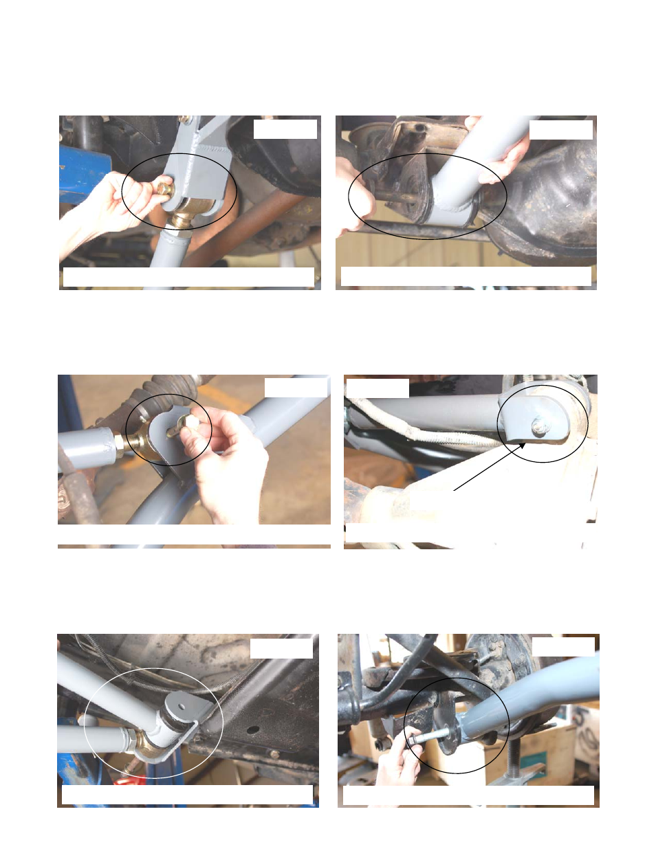
32. Install the new front lower control arm in the new mount with the supplied 9/16” x 4” bolts, washers / nuts making
sure the joint is centered. Do not tighten at this time. See Photo 16.
33. Install the lower control arm on the axle with the factory hardware. See Photo 17. Do not tighten at this time.
34. Assemble the front upper control arm and adjust to a length of 15 1/4” from center of hole to center of bushing.
Install on the new lower control arm with the supplied 10mm x 80mm bolt, washers / nuts. See Photo 18. Do not
tighten at this time. Tighten jam nut using an adjustable wrench.
35. Install the new upper arm to the axle using the supplied 10mm x 80mm bolt, washers & nuts. Do not tighten at
this time. See Photo 19. If installing on a vehicle equipped with a Dana 44 front axle, be sure to install the
arm on the drivers side with the cut out over the differential to allow clearance. See Photo 19.
36. Moving to the rear of the Jeep, Grease the supplied bushings with a lithium grease and install the bushings in the
rear upper and lower control arms. Adjust the lower control arms to 27 3/4” and the upper control arms to 29”
long. On LJ Jeeps: Adjust the lower arms to 38 3/4” and adjust the upper control arms to 39”.
37. Install the new rear lower & upper control arm in the new mount with the supplied 9/16” x 7” bolts. Washers / nuts
making sure the lower arm joint is centered in the mount. Do not tighten at this time. See Photo 20.
38. If installing on a Rubicon Model, reinstall the compressor bracket on the bolt as shown in Step 28.
PHOTO 16
PHOTO 17
Install the lower control arms with 9/16” x 4” bolts
Install the lower arm to axle with stock hardware
PHOTO 18
PHOTO 19
Install the upper arm to lower using 10MM X 80MM bolts
Install upper arm to axle with 10mm x 80mm bolts
Cut out on driver side shown
PHOTO 20
Install arms to bracket using 9/16” x 7” bolt
PHOTO 21
Install the arm to axle with stock hardware