Rough Country 379.22 User Manual
Page 2
FRONT SUSPENSION INSTALLATION
1. Secure and block the rear tires of the vehicle on a level concrete or asphalt surface
2. Open the hood and remove the shock nuts, retaining washers and rubber bushings from both upper shock mounts
located inside the engine compartment. The shocks will be removed when the coils are removed.
3. Raise the front of the vehicle and support the frame with jack stands. Remove the front wheels and tires and set
aside. Position a hydraulic jack under the front axle and raise the jack until the front suspension begins to com-
press
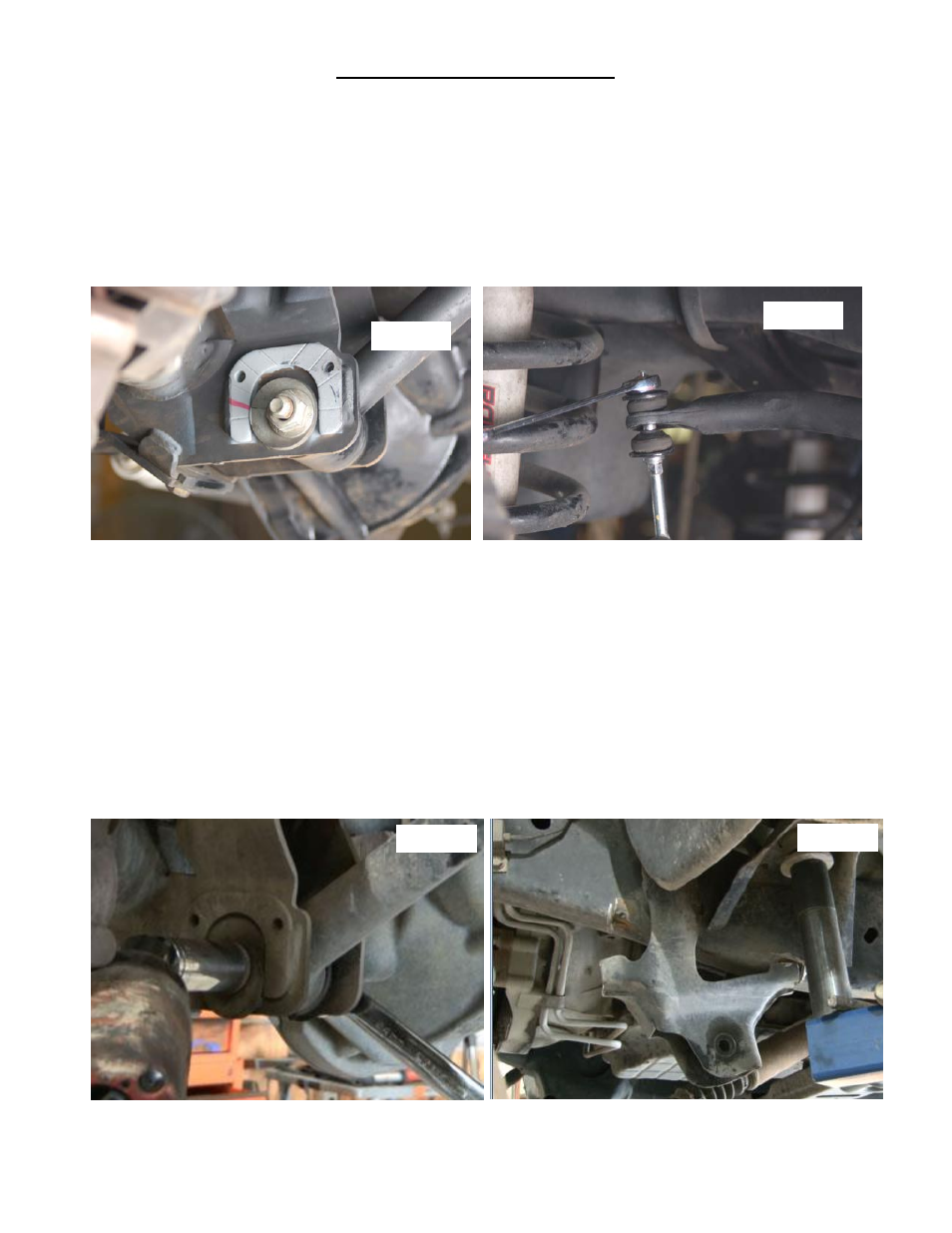
4. On both sides of the vehicle, scribe alignment marks on the adjustment cam and axle bracket at the lower link to
axle attachment point for later reference.
See Photo 1.
5. Unbolt the brake line brackets from the control arm mount on the axle using a 13mm wrench to ensure brake line
free play during the suspension system installation.
6. Loosen the stock front upper sway bar links on the sway bar as shown in
Photo 2 using a 15mm wrench.
7. Remove the track bar from its upper mounting point on the frame using a 24mm wrench and rest it on the axle. It
may be helpful to loosen the lower track bar bolt on the axle. Retain hardware for reuse.
8. Remove the cotter pin, and castle nut from the drag link where it connects to the pitman arm. A pitman arm tool
may be needed to separate the drag link from the pitman arm. Remove the stock nut, and lock washer from the
sector shaft on the steering box. Save hardware for later installation. Using a pitman arm puller carefully remove
the stock pitman arm.
9. The new control arms will be installed one side at a time on the vehicle. This is done to make it easier to remove
the hardware from the arms and to not cause bind in the front suspension. Remove the lower suspension arm nut,
cam, and cam bolt from the axle using a 21mm and a 24mm socket and wrench. Remove the nut and bolt from the
frame attachment point and remove the lower suspension arm from the vehicle.
See Photo 3. Retain hardware for
reuse.
10. Using a 21mm socket remove the upper control arm from the axle and frame. Note
—the passenger side upper
control arm frame bolt will have to be cut or remove the exhaust before the bolt can be removed.
11. Use a cut off wheel on a die grinder and cut the welds around the lower control arm frame bracket. The frame
bracket has to be removed to allow clearance for the new longer arms.
See Photo 4.
12. After the factory bracket has been removed grind the frame smooth and paint to prevent rust.
13. Support the transmission cross member with a jack and remove the two bolts on end with a 18mm socket and a
21mm wrench.
Photo 1
Photo 2
Photo 4
Photo 3