Overview, Connection – Velleman CU2200 User Manual
Page 3
CU2200
v
3-02
26.10.2012
©
Velleman nv
3
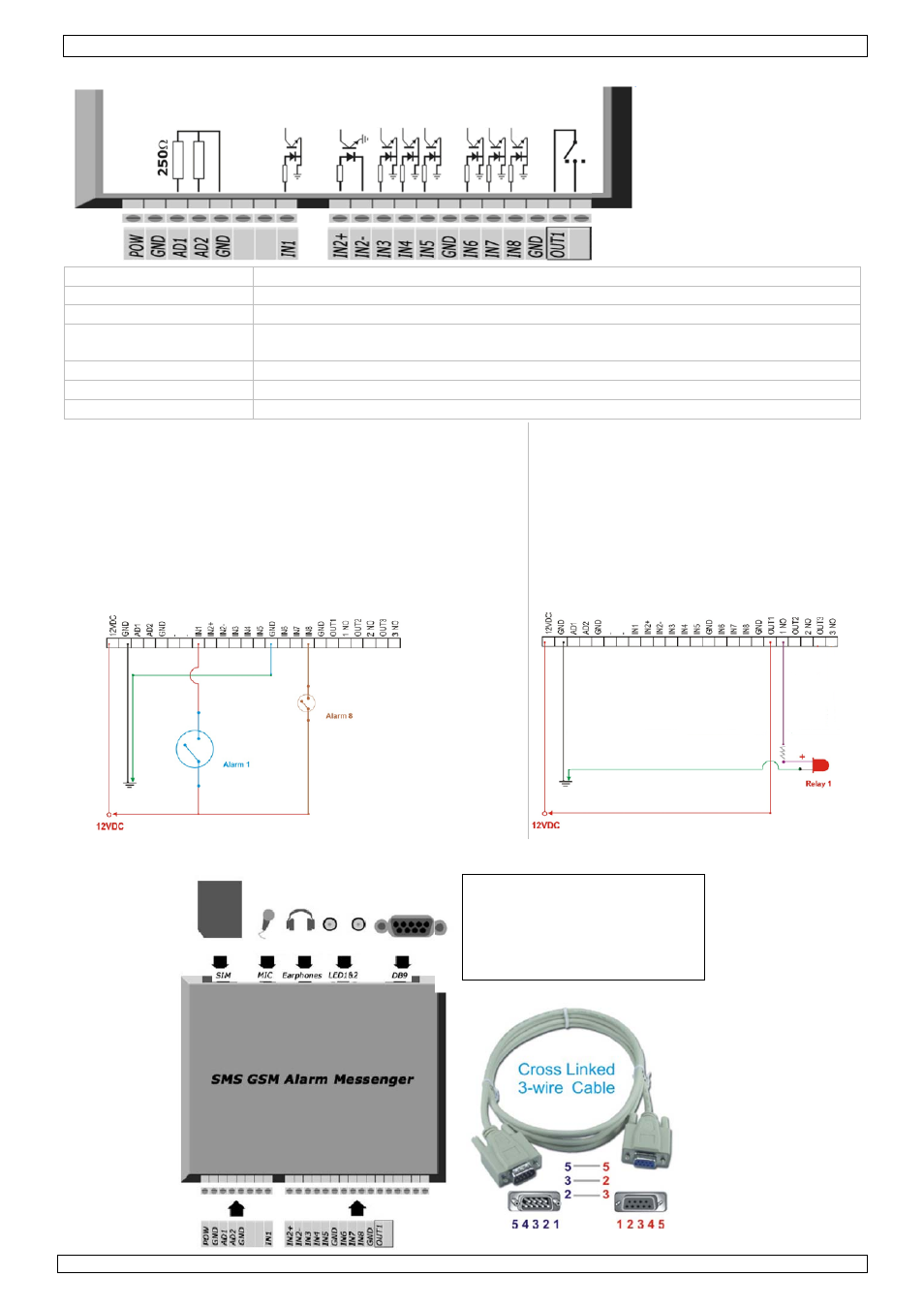
5. Overview
OUT1
Relay output jumper
1 2 3
▪
▪
▪
1-2 short NC
2-3 short NO (default)
POW
7~12VDC power input
GND
ground
AD1, AD2
these inputs are not supported on the CU2200
IN1, IN3, IN4,
IN5, IN6, IN7, IN8
12VDC alarm input, 7~15mA
GND
common ground opto-coupled
IN2+, IN2-
7~12VDC input
OUT1
relay output, max. 1A, 24VDC, 1A, 120VAC, NC/NO (selected by jumper on board)
Alarm Input
• 12VDC, 7 ~ 15m, Opto-isolated Inputs (1kΩ Input
Resistance)
• 24VDC, resistor 1 ~ 2,2kΩ should be used in serial
(a) IN1, IN3, IN4, IN5, IN6, IN7, IN8
Alarm Input: DC12V 7 ~ 15mA, GND: Common Ground
(b) IN2+, IN2-
IN2+:DC5 ~ 12V
IN2-: Ground [It must NOT be common to the GND of the
board]
Relay Output
OUT1, OUT2, OUT3:
Max. 1A, 24VDC / 1A, 120VAC
NC/NO (selected by jumper on board)
Note: OUT2 and OUT3 are not available
on CU2200
6. Connection
RS232 pin assignment
9600bps, 8bit, no parity, 1 stop
pin 2 RxD
pin 3 TxD
pin 5 GND