Vishay semiconductors – C&H Technology 70MT060WSP User Manual
Page 7
70MT060WSP
www.vishay.com
Vishay Semiconductors
Revision: 07-Sep-11
6
Document Number: 93410
For technical questions within your region:
,
,
THIS DOCUMENT IS SUBJECT TO CHANGE WITHOUT NOTICE. THE PRODUCTS DESCRIBED HEREIN AND THIS DOCUMENT
ARE SUBJECT TO SPECIFIC DISCLAIMERS, SET FORTH AT
www.vishay.com/doc?91000
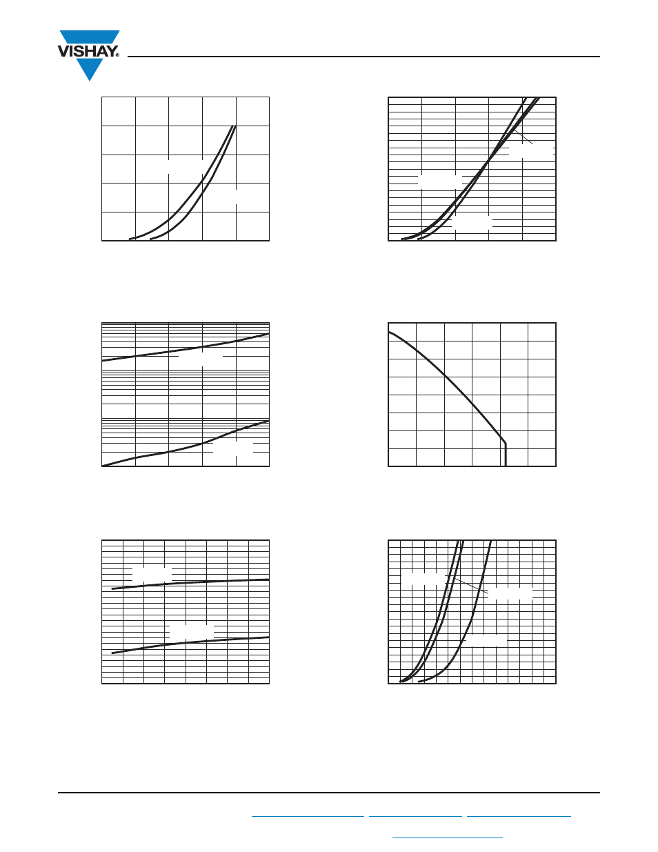
Fig. 10 - Typical IGBT Transfer Characteristics, T
J
= 125 °C
Fig. 11 - Typical IGBT Zero Gate Voltage Collector Current
Fig. 12 - Typical IGBT Gate Thresold Voltage
Fig. 13 - Typical Diode Forward Voltage Characteristics of
Antiparallel Diode, t
p
= 500 μs
Fig. 14 - Maximum Continuous Forward Current vs.
Case Temperature Antiparallel Diode
Fig. 15 - Typical PFC Diode Forward Voltage
I
C
(A)
V
GE
(V)
3
4
5
6
7
8
0
93410_10
250
50
150
100
200
T
C
= 125 °C
T
C
= 25 °C
I
CE
S
(mA)
V
CES
(V)
100
600
200
300
400
500
0.001
93410_11
1
0.1
0.01
T
C
= 125 °C
T
C
= 25 °C
V
geth
(V)
I
C
(mA)
0.2
1.0
0.3
0.4
0.6
0.8
0.5
0.7
0.9
2.0
2.5
3.0
3.5
4.0
93410_12
4.5
T
C
= 125 °C
T
C
= 25 °C
I
F
- Instantaneous Forwar
d
Current (A)
V
F
- Anode to Cathode
Forward Voltage Drop (V)
0.5
1.0
1.5
2.0
2.5
3.0
0
60
100
90
40
80
20
50
30
10
70
93410_13
T
J
= 150 °C
T
J
= 125 °C
T
J
= 25 °C
Allowable Case Temperature (°C)
I
F
- Continuous Forward Current (A)
20
15
10
5
25
30
0
80
120
160
140
0
40
60
100
20
93410_14
I
F
- Instantaneous Forwar
d
Drop (A)
V
F
- Forward Voltage Drop (V)
0.25
0.75
1.25
2.25
1.75
2.75
3.75
3.25
0
90
30
50
70
40
10
20
60
80
100
93410_15
T
J
= 25 °C
T
J
= 125 °C
T
J
= 150 °C