Vishay semiconductors – C&H Technology 70MT060WSP User Manual
Page 6
70MT060WSP
www.vishay.com
Vishay Semiconductors
Revision: 07-Sep-11
5
Document Number: 93410
For technical questions within your region:
,
,
THIS DOCUMENT IS SUBJECT TO CHANGE WITHOUT NOTICE. THE PRODUCTS DESCRIBED HEREIN AND THIS DOCUMENT
ARE SUBJECT TO SPECIFIC DISCLAIMERS, SET FORTH AT
www.vishay.com/doc?91000
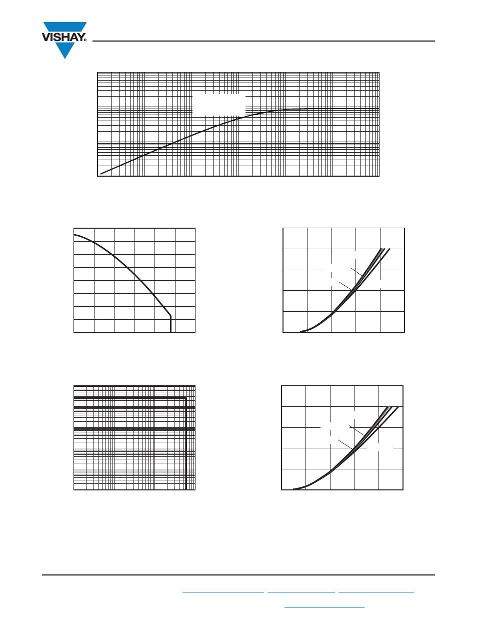
Fig. 5 - Maximum Input Bridge Thermal Impedance Z
thJC
Characteristics (Per Junction)
Fig. 6 - Maximum IGBT Continuous Collector Current vs.
Case Temperature
Fig. 7 - IGBT Reverse BIAS SOA T
J
= 150 °C, V
GE
= 15 V
Fig. 8 - Typical IGBT Output Characteristics, T
J
= 25 °C
Fig. 9 - Typical IGBT Output Characteristics, T
J
= 125 °C
0.01
0.1
1
10
0.00001
93410_05
0.0001
0.001
0.01
0.1
1
t
1
- Rectangular Pulse Duration (s)
Z
thJC
- Thermal Impe
d
ance (°C/W)
10
Steady state value
R
thJC
= 0.9 °C/W
(DC operation)
Allowable Case Temperature (°C)
I
D
- Continuous Collector Current (A)
80
100
60
40
20
120
0
100
160
0
40
60
140
80
120
20
93410_06
I
C
(A)
V
CE
(V)
1
10
100
1000
0.01
0.1
1
93410_07
1000
10
100
I
C
(A)
V
CE
(V)
0
1
2
3
4
5
0
93410_08
250
50
150
100
200
V
GE
= 9 V
V
GE
= 12 V
V
GE
= 15 V
V
GE
= 18 V
I
C
(A)
V
CE
(V)
0
1
2
3
4
5
0
93410_09
250
50
150
100
200
V
GE
= 9 V
V
GE
= 12 V
V
GE
= 15 V
V
GE
= 18 V