Vishay semiconductors, Thermal and mechanical specifications – C&H Technology 70MT060WSP User Manual
Page 5
70MT060WSP
www.vishay.com
Vishay Semiconductors
Revision: 07-Sep-11
4
Document Number: 93410
For technical questions within your region:
,
,
THIS DOCUMENT IS SUBJECT TO CHANGE WITHOUT NOTICE. THE PRODUCTS DESCRIBED HEREIN AND THIS DOCUMENT
ARE SUBJECT TO SPECIFIC DISCLAIMERS, SET FORTH AT
www.vishay.com/doc?91000
Notes
• A mounting compound is recommended and the torque should be rechecked after a period of 3 hours to allow for the spread of the
compound. Lubricated threads.
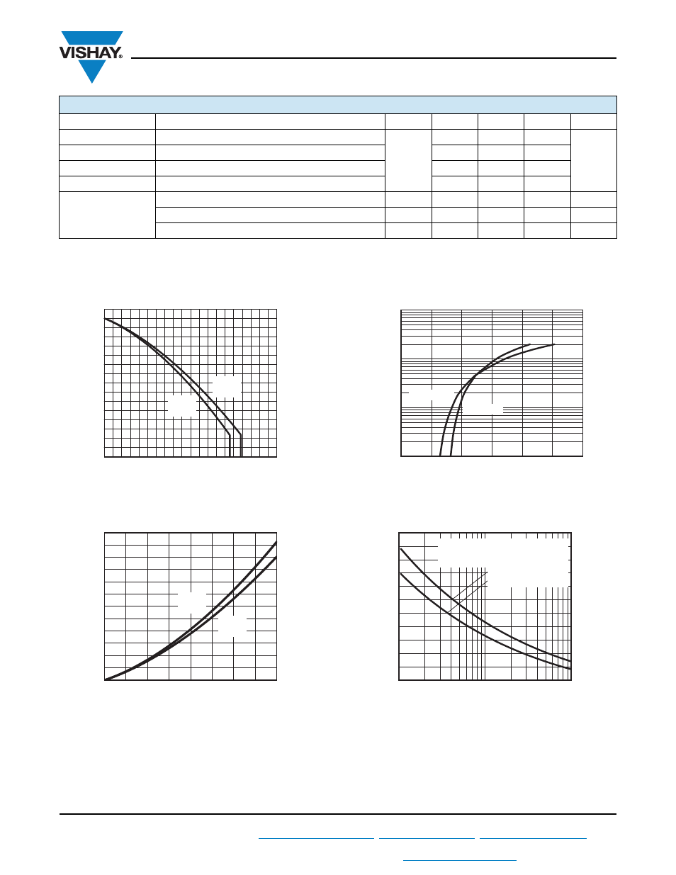
Fig. 1 - Single Phase Input Bridge Output
Current Ratings Characteristics
Fig. 2 - Single Phase Bridge On-State Power
Loss Characteristics
Fig. 3 - Single Phase Input Bridge On-State
Voltage Drop Characteristics
Fig. 4 - Single Phase Input Bridge Maximum
Non-Repetitive Surge Current (Per Junction)
THERMAL AND MECHANICAL SPECIFICATIONS
PARAMETER SYMBOL
MIN.
TYP. MAX. UNITS
Input Rectifier Bridge
Junction to case diode thermal resistance
R
thJC
-
-
0.9
°C/W
PFC IGBT
Junction to case IGBT thermal resistance
-
-
0.33
PFC Diode
Junction to case PFC diode thermal resistance
-
-
0.69
AP Diode
Junction to case AP diode thermal resistance
-
-
3.92
Case to sink, flat, greased surface per module
R
thCS
-
0.06
-
°C/W
Mounting torque ± 10 % to heatsink
(1)
-
-
4
Nm
Approximate weight
-
65
-
g
Maximum Allowable Case
Temperature (°C)
Average Output Current (A)
50
40
20
30
10
60
70
80
90 100
0
80
120
160
0
93410_01
40
60
100
140
20
180°
(Rect.)
180°
(Sine)
Maximum Average On-
S
tate
Power Loss (W)
Total Output Current (A)
50
40
30
20
10
60
80
70
0
200
300
0
93410_02
100
150
250
50
180°
(Sine)
180°
(Rect.)
Instantaneous On-
S
tate Current (A)
Instantaneous Voltage Drop (V)
1
2
3
0
93410_03
1000
100
10
1
T
J
= 25 °C
T
J
= 150 °C
Peak Half
S
ine Wave
On-
S
tate Current (A)
Pulse Train Duration (s)
0.1
1
0.01
93410_04
325
50
75
125
175
225
275
100
150
200
250
300
At any rated load condition and with
rated V
RRM
applied following surge.
Initial T
J
= T
J
max.
No voltage reapplied
Rated V
RRM
reapplied