40epf..pbf soft recovery series, Vishay high power products, Fast soft recovery rectifier diode, 40 a – Vishay 40EPF..PbF Soft Recovery Series User Manual
Page 2: Electrical specifications, Recovery characteristics, Thermal - mechanical specifications
www.vishay.com
For technical questions, contact: [email protected]
Document Number: 94102
2
Revision: 14-Apr-08
40EPF..PbF Soft Recovery Series
Vishay High Power Products
Fast Soft Recovery
Rectifier Diode, 40 A
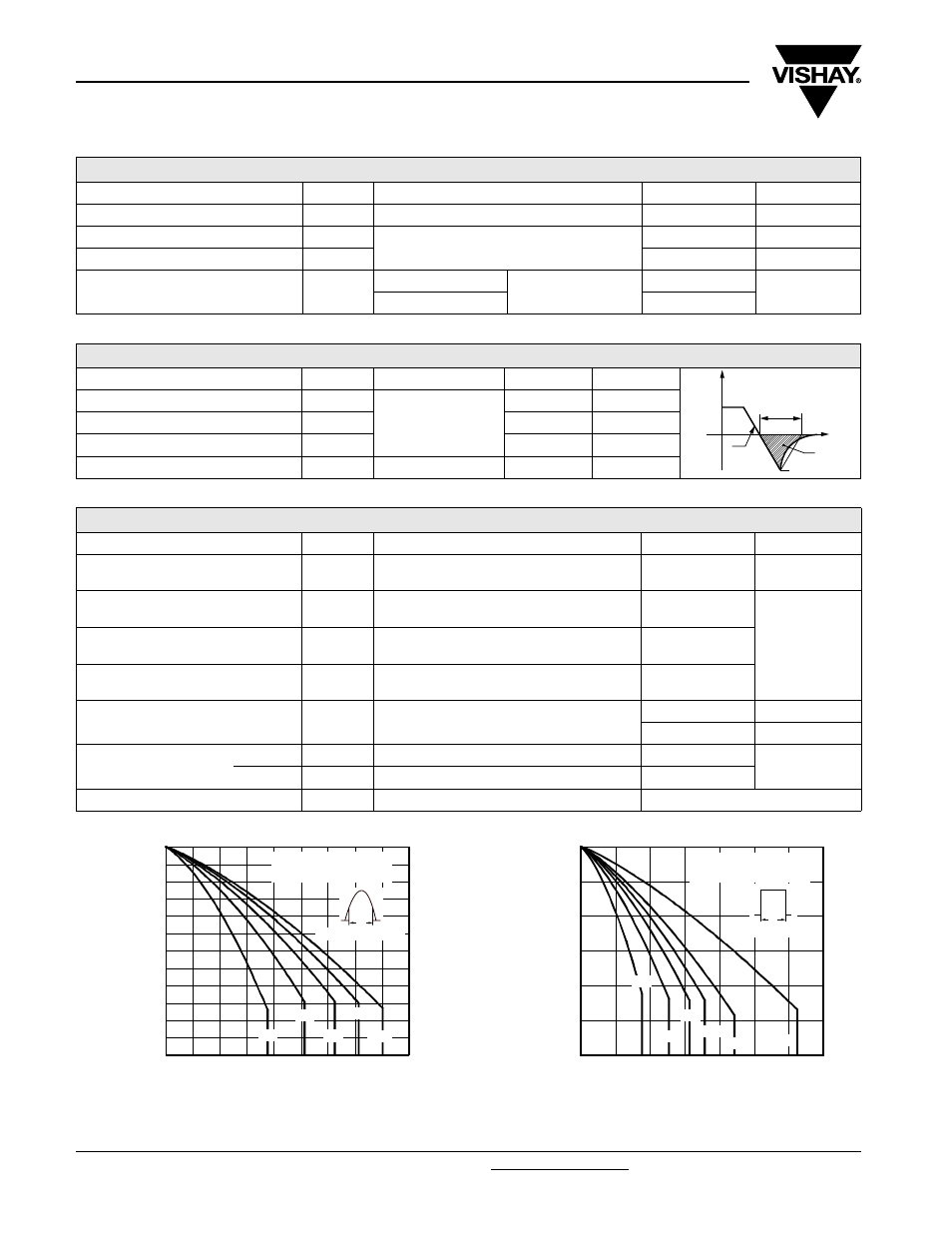
Fig. 1 - Current Rating Characteristics
Fig. 2 - Current Rating Characteristics
ELECTRICAL SPECIFICATIONS
PARAMETER SYMBOL
TEST
CONDITIONS
VALUES
UNITS
Maximum forward voltage drop
V
FM
40 A, T
J
= 25 °C
1.25
V
Forward slope resistance
r
t
T
J
= 125 °C
4.4
m
Ω
Threshold voltage
V
F(TO)
1.1
V
Maximum reverse leakage current
I
RM
T
J
= 25 °C
V
R
= Rated V
RRM
0.1
mA
T
J
= 150 °C
7.0
RECOVERY CHARACTERISTICS
PARAMETER
SYMBOL
TEST CONDITIONS
VALUES
UNITS
Reverse recovery time
t
rr
I
F
at 40 Apk
25 A/µs
25 °C
180
ns
Reverse recovery current
I
rr
3.2
A
Reverse recovery charge
Q
rr
0.5
µC
Snap factor
S
0.5
I
FM
t
rr
dir
dt
I
RM(REC)
Q
rr
t
THERMAL - MECHANICAL SPECIFICATIONS
PARAMETER
SYMBOL
TEST CONDITIONS
VALUES
UNITS
Maximum junction and storage
temperature range
T
J
, T
Stg
- 40 to 150
°C
Maximum thermal resistance,
junction to case
R
thJC
DC
operation
0.6
°C/W
Maximum thermal resistance,
junction to ambient
R
thJA
40
Typical thermal resistance,
case to heatsink
R
thCS
Mounting surface, smooth and greased
0.2
Approximate weight
6
g
0.21
oz.
Mounting torque
minimum
6 (5)
kgf · cm
(lbf · in)
maximum
12 (10)
Marking device
Case style TO-247AC modified (JEDEC)
40EPF06
150
0
Maxim
um Allo
w
ab
le Case
T
e
mperature (°C)
Average Forward Current (A)
5
100
10
45
120
130
110
15
25
140
35
20
Conduction angle
40EPF.. Series
R
thJC
(DC) = 0.6 K/W
90
30°
60°
90°
120°
180°
40
30
Ø
150
0
30
Maxim
um Allo
w
ab
le Case
T
e
mperature (°C)
Average Forward Current (A)
50
110
70
120
10
20
130
140
40EPF.. Series
R
thJC
(DC) = 0.6 K/W
Ø
Conduction period
30°
60°
90°
120°
180°
DC
100
90
60
40