40epf.. soft recovery series, Vishay high power products, Fast soft recovery rectifier diode, 40 a – Vishay 40EPF.. Soft Recovery Series User Manual
Page 3
Document Number: 93149
For technical questions, contact: [email protected]
www.vishay.com
Revision: 13-Jun-08
3
40EPF.. Soft Recovery Series
Fast Soft Recovery
Rectifier Diode, 40 A
Vishay High Power Products
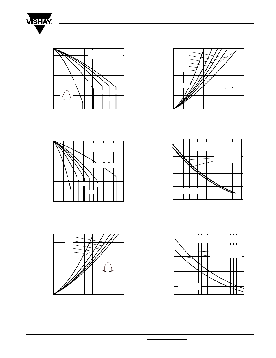
Fig. 1 - Current Rating Characteristics
Fig. 2 - Current Rating Characteristics
Fig. 3 - Forward Power Loss Characteristics
Fig. 4 - Forward Power Loss Characteristics
Fig. 5 - Maximum Non-Repetitive Surge Current
Fig. 6 - Maximum Non-Repetitive Surge Current
0
15
Maxim
um Allo
wab
le Case
T
e
mperature (°C)
Average Forward Current (A)
10
5
20
25
30
35
40
45
60
70
80
90
100
110
120
130
140
150
60°
30°
90°
180°
40EPF.. Series
R
thJC
(DC) = 0.6 °C/W
120°
Conduction angle
Ø
0
Maxim
um Allo
wab
le Case
T
emperature (°C)
Average Forward Current (A)
30
10
20
40
50
60
70
60
70
80
90
100
110
120
130
140
150
40EPF.. Series
R
thJC
(DC) = 0.6 °C/W
Ø
Conduction period
30°
60°
DC
90°
120°
180°
0
0
Maxim
um A
vera
g
e Forwar
d
P
o
wer Loss (W)
Average Forward Current (A)
20
25
30
35
40
45
10
15
5
10
20
30
40
50
60
70
RMS limit
180°
120°
90°
60°
30°
Conduction angle
40EPF.. Series
T
J
= 150 °C
Ø
Maxim
um A
vera
g
e Forwar
d
P
o
wer Loss (W)
Average Forward Current (A)
0
0
20
30
40
50
60
70
10
10
20
30
40
50
60
70
80
90
RMS limit
Ø
Conduction period
40EPF.. Series
T
J
= 150 °C
DC
180°
120°
90°
60°
30°
1
10
100
P
e
ak Half Sine
W
a
ve
Forwar
d Current (A)
Number of Equal Amplitude Half Cycle
Current Pulses (N)
100
150
200
250
300
350
400
450
Initial T
J
= 150 °C
at 60 Hz 0.0083 s
at 50 Hz 0.0100 s
At any rated load condition and with
rated V
RRM
applied following surge.
40EPF.. Series
0.01
0.1
1
P
e
ak Half Sine
W
a
ve
Forwar
d Current (A)
Pulse Train Duration (s)
100
150
200
250
300
350
400
450
500
Initial T
J
= 150 °C
No voltage reapplied
Rated V
RRM
reapplied
Maximum non-repetitive surge current
versus pulse train duration.
40EPF.. Series