Vishay semiconductors, Standard recovery diodes, 400 a preliminary – Vishay VSMD400AW60 User Manual
Page 2
www.vishay.com
For technical questions, contact:
Document Number: 93469
2
Revision: 21-Dec-10
VSMD400AW60, VSMD400CW60
Vishay Semiconductors
Standard Recovery Diodes, 400 A
Preliminary
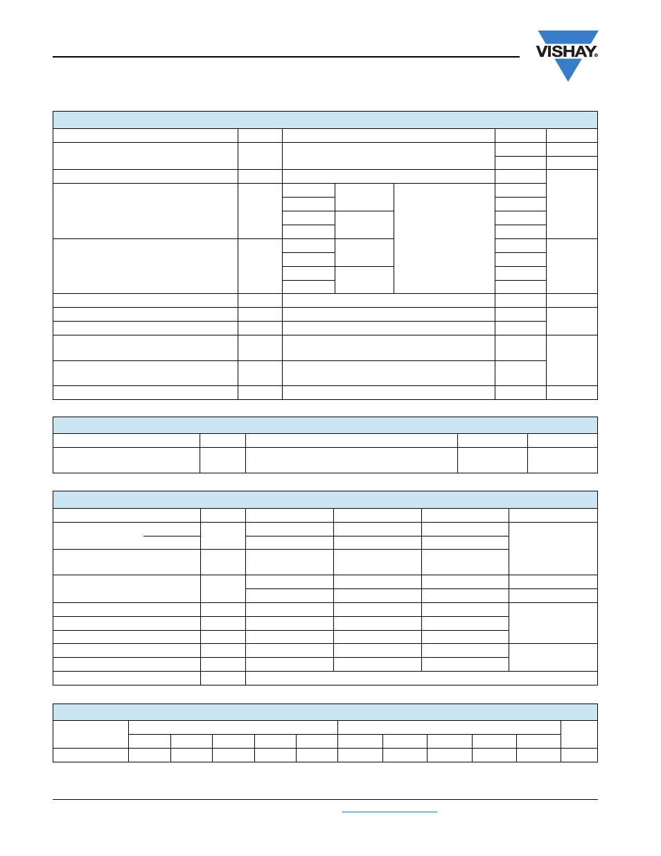
Note
• Table shows the increment of thermal resistance R
thJC
when devices operate at different conduction angles than DC
FORWARD CONDUCTION
PARAMETER
SYMBOL
TEST CONDITIONS
VALUES
UNITS
Maximum average forward current at case
temperature per leg
I
F(AV)
180° conduction, half sine wave
200
A
133
°C
Maximum RMS forward current per leg
I
F(RMS)
DC at 137 °C case temperature
314
A
Maximum peak, one-cycle forward,
non-repetitive surge current per leg
I
FSM
t = 10 ms
No voltage
reapplied
Sinusoidal half wave,
initial T
J
= T
J
maximum
2500
t = 8.3 ms
2620
t = 10 ms
100 % V
RRM
reapplied
2100
t = 8.3 ms
2200
Maximum I
2
t for fusing per leg
I
2
t
t = 10 ms
No voltage
reapplied
32
kA
2
s
t = 8.3 ms
29
t = 10 ms
100 % V
RRM
reapplied
22
t = 8.3 ms
20
Maximum I
2
√t for fusing per leg
I
2
√t
t = 0.1 ms to 10 ms, no voltage reapplied
311
kA
2
√s
Low level value of threshold voltage per leg
V
F(TO)1
(16.7 % x
π x I
F(AV)
< I <
π x I
F(AV)
), T
J
= T
J
maximum
0.73
V
High level value of threshold voltage per leg
V
F(TO)2
(I >
π x I
F(AV)
), T
J
= T
J
maximum
0.85
Low level value of forward
slope resistance per leg
r
f1
(16.7 % x
π x I
F(AV)
< I <
π x I
F(AV)
), T
J
= T
J
maximum
1.52
m
Ω
High level value of forward
slope resistance per leg
r
f2
(I >
π x I
F(AV)
), T
J
= T
J
maximum
1.36
Maximum forward voltage drop per leg
V
FM
I
FM
= 200 A, T
J
= 25 °C, t
p
= 400 μs square wave
1.31
V
BLOCKING
PARAMETER
SYMBOL
TEST CONDITIONS
VALUES
UNITS
Maximum peak reverse leakage
current per module
I
RRM
T
J
= 175 °C
12
mA
THERMAL AND MECHANICAL SPECIFICATIONS
PARAMETER
SYMBOL
MIN.
TYP.
MAX.
UNITS
Thermal resistance,
junction to case
per leg
R
thJC
-
-
0.10
°C/W
per module
-
-
0.05
Thermal resistance,
case to heatsink per module
R
thCS
-
0.10
-
Weight
-
68
-
g
-
2.4
-
oz.
Mounting torque
30 (3.4)
-
40 (4.6)
lbf · in
(N · m)
Mounting torque center hole
12 (1.4)
-
18 (2.1)
Terminal torque
30 (3.4)
-
40 (4.6)
Vertical pull
-
-
80
lbf · in
2” lever pull
-
-
35
Case style
TO-244
ΔR CONDUCTION PER JUNCTION
DEVICES
SINE HALF WAVE CONDUCTION
RECTANGULAR WAVE CONDUCTION
UNITS
180°
120°
90°
60°
30°
180°
120°
90°
60°
30°
VSMD400.W60
0.041
0.047
0.060
0.084
0.131
0.029
0.049
0.064
0.087
0.132
°C/W