Fig. 1 altv244ul, Back panel of enclosure, Back panel of enclosure fig. 2 altv244ulcb – Altronix ALTV244ULCB3 Installation Instructions User Manual
Page 4: Xfmr
- 4 -
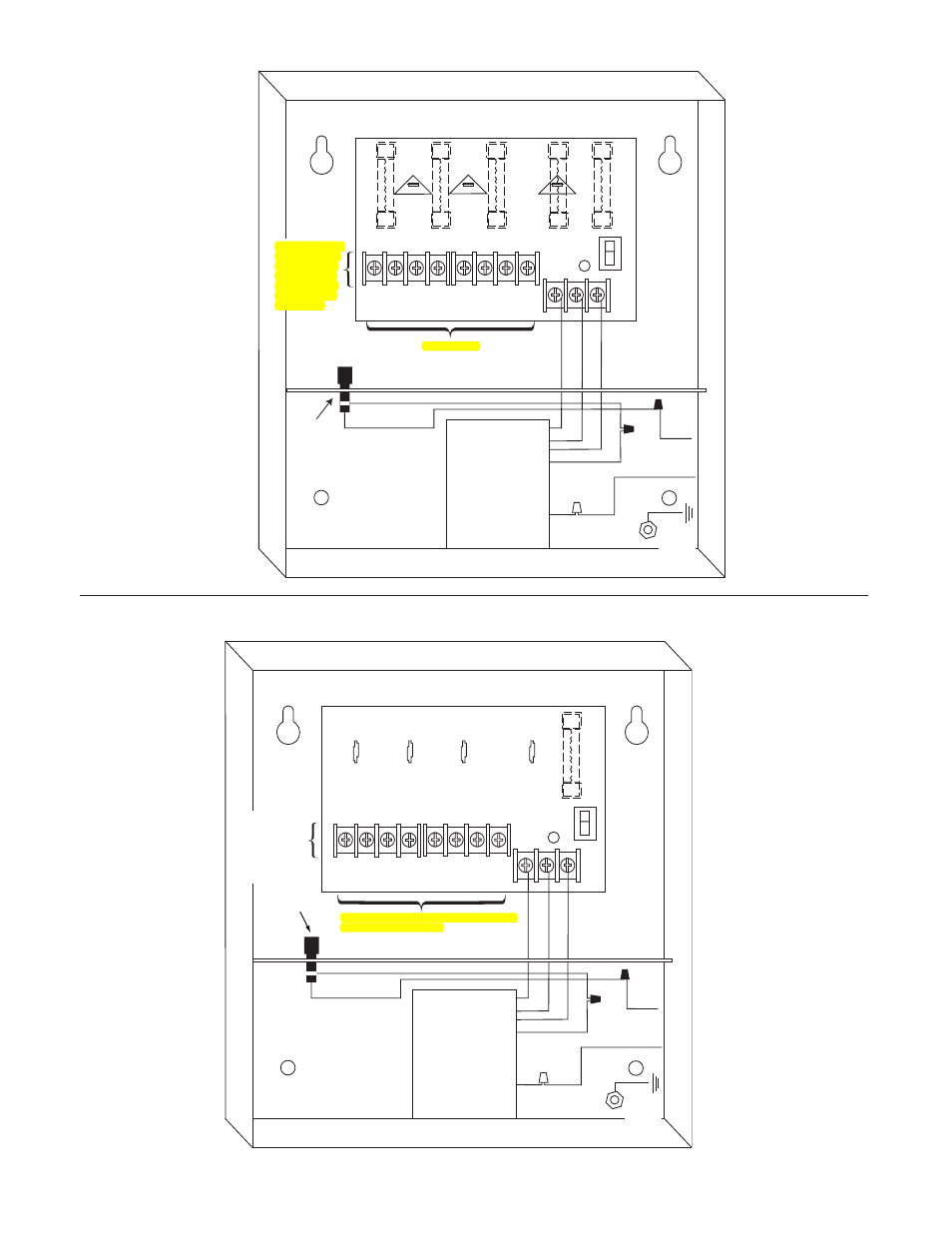
Fig. 1
ALTV244UL
1P
1N
2P
2N
3P
3N
4P
4N
LED
3.5A 250V
3.5A 250V
3.5A 250V
XFMR
White
Lead
Black
Lead
Black
Lead
non-power
limited
non-power
limited
115VAC
Input
50/60 Hz.
O
N
O
F
F
SW1
INPUT
NP
S
Green
Lead
(Ground)
M
A
IN
F
U
S
E
Primary
In-line
Fuse
Class 1 Outputs
24VAC or 28VAC
output 1 (Follow
same procedure
using terminals
2P & N through
4P & N outputs
2 through 4)
Back Panel
of Enclosure
F1
F2
F3
F4
INPUT
1P
1N
2P
2N
3P
3N
4P
4N
LED
O
N
O
F
F
SW1
NP
S
M
A
IN
F
U
S
E
XFMR
White
Lead
Black
Lead
Black
Lead
non-power
limited
non-power
limited
115VAC
Input
50/60 Hz.
Green
Lead
(Ground)
Primary
In-line
Fuse
24VAC configuration Class 2 Not Wet/Class 3 Wet
28VAC configuration Class 1
24VAC or 28VAC
output 1
(Follow same
procedure using
terminals 2P & N
through 4P & N
outputs 2 through 4)
Back Panel
of Enclosure
Fig. 2
ALTV244ULCB
See also other documents in the category Altronix Accessories for electrical:
- NetWay3012 Installation Instructions (2 pages)
- HubWay 16Di Data Sheet (2 pages)
- Maximal77 Installation Instructions (20 pages)
- HubWay Dvi Data Sheet (1 page)
- HubWay Av2 Data Sheet (1 page)
- PD4CB Installation Instructions (1 page)
- ACM4CB Data Sheet (2 pages)
- VertiLine63D Data Sheet (2 pages)
- eBridge16CR Installation Instructions (8 pages)
- LPS3WP12 Data Sheet (2 pages)
- VertiLine246D Data Sheet (2 pages)
- T24130D Data Sheet (1 page)
- eBridge1PCRTX Data Sheet (2 pages)
- RB5 Installation Instructions (1 page)
- Tempo2 Data Sheet (1 page)
- BC600G Data Sheet (1 page)
- eBridge1CRT Data Sheet (2 pages)
- AL400ULB Data Sheet (1 page)
- PT2724 Installation Instructions (8 pages)
- OLS180 Installation Instructions (2 pages)
- HubWay 8CD Data Sheet (2 pages)
- AL175ULB Data Sheet (1 page)
- StrikeIt2 Installation Instructions (8 pages)
- LPD Data Sheet (1 page)
- eBridge4SK Installation Instructions (8 pages)
- LPS3AC Installation Instructions (2 pages)
- T2428100 Data Sheet (1 page)
- TP1650 Data Sheet (1 page)
- T2885D Data Sheet (1 page)
- T2428175 Installation Instructions (1 page)
- T1656 Installation Instructions (1 page)
- SMP3 Data Sheet (1 page)
- RBR1224 Data Sheet (1 page)
- HubWay LD16D Data Sheet (2 pages)
- eFlow102NX16D Installation Instructions (16 pages)
- T24175C Data Sheet (1 page)
- Maximal5D Data Sheet (2 pages)
- Maximal7 Installation Instructions (16 pages)
- HubWay 8CDS Data Sheet (2 pages)
- eFlow4NX8D Installation Instructions (16 pages)
- MOM5C Data Sheet (1 page)
- eBridge16PCRX Installation Instructions (8 pages)
- HubWay EX16SP Data Sheet (2 pages)
- T24130C Installation Instructions (1 page)
- Maximal5 Data Sheet (2 pages)