Fig. 1 fig. 1a, Power supply board, Power distribution module(s) – Altronix SMP10PMC12X Installation Instructions User Manual
Page 2
- 2 -
SMP1012Xseries
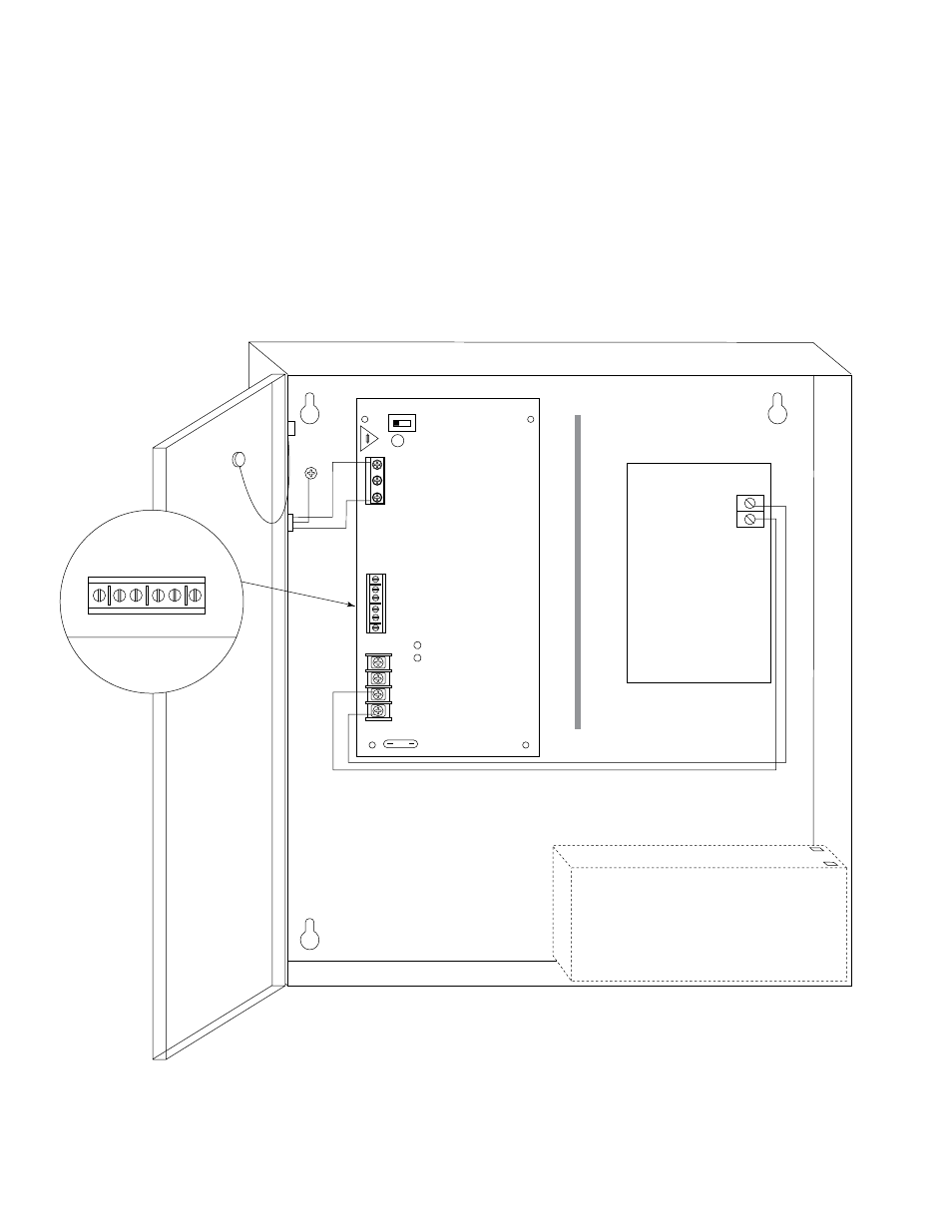
4. Connect devices to be powered: a. For Power Supply Board connect to the terminals marked [– DC +].
b. For Power Distribution Module(s) connect devices to be powered to the terminal pairs 1 to 4 marked
[1P & 1N through 4P & 4N] (Fig. 3, pg. 4) 1 to 8 marked [1P & 1N through 8P & 8N] (Fig. 4, pg. 4)
or 1 to 16 marked [1P & 1N through 16P & 16N] (Fig. 5, pg. 4), carefully observing correct polarity.
*Note: Power switch is used to disconnect the L (HOT) terminal from the rest of the board. When servicing the unit,
AC mains should be removed.
5. When using stand-by batteries, they must be lead acid or gel type. Connect battery to the terminals marked [– BAT +]
(battery leads included).
Note: When batteries are not used, a loss of AC will result in the loss of output voltage.
6. Connect appropriate signaling notification devices to the AC Fail & Low Bat supervisory relay outputs
marked [NC, C, NO] (Fig. 1a, below).
Power Supply
Board
LG
N
OFF ON
LOW BAT
NC C NO NC C NO
AC FAIL
---
BA
T +
---
DC
+
AC
DC
5A
250V
15
A
Power
Distribution
Module(s)
Earth
Ground
Wire
Strap
(from
Enclosure
to Door)
115 power
mains
INPUT
Divider
LOW BA
T
NC C NO NC C NO
AC F
AIL
CAUTION: De-energize unit prior to servicing. For continued protection
against fire hazard replace fuse with the same type and rating, 15A, 32V.
12VDC Rechargeable Battery
(optional)
CAUTION: Optional rechargeable stand-by batteries must match the power supply
output voltage setting.
Keep power-limited wiring separate from non power-limited. Use minimum 0.25" spacing.
Fig. 1
Fig. 1a