Eflow6n series - 7, Switch detail – Altronix eFlow6N_NX Series Installation Instructions User Manual
Page 7
eFlow6N Series
- 7 -
L
G
N
NC
C
NO
NC
C
NO
BA
T F
AIL
AC F
AIL
--- DC +
AC
AC1
DC
--- BAT +
– AUX
+
TRIGGER EO
L
SUPER
VISE
D
5A 250V
RESE
T
GND NO
OPEN --- 24V
CLOSED --- 12V
disable
enable
2 hr
.
1 min
.
AC DELAY
SHUTDOWN
O N
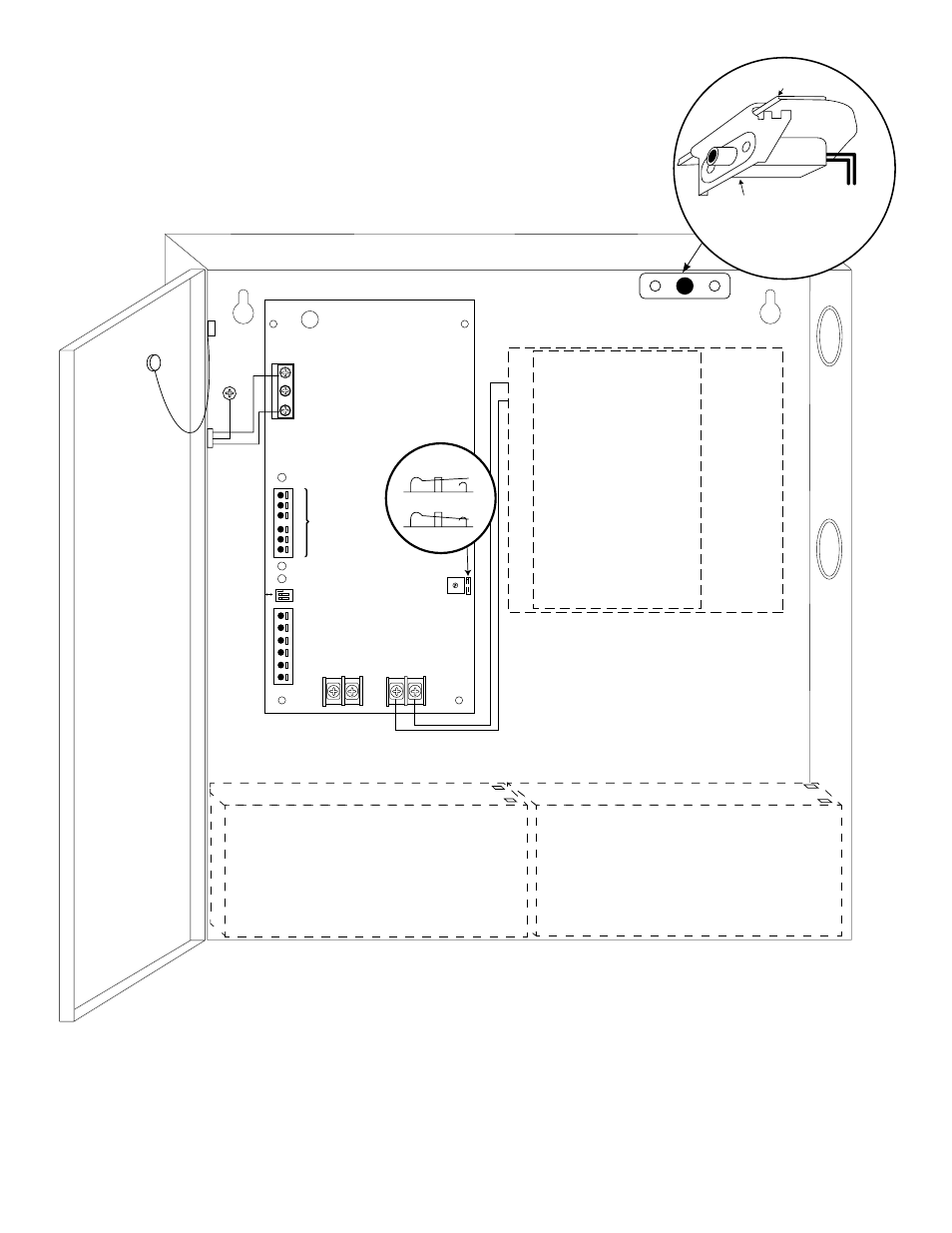
Door
Wire
Strap
(from
Enclosure
to Door)
CAUTION: When power supply board is set for 12VDC use only one (1) 12VDC stand-by battery.
Keep power-limited wiring separate from non power-limited. Use minimum 0.25" spacing.
7AH Rechargeable batteries are the largest batteries that can fit in this enclosure.
A UL Listed external battery enclosure must be used if using 12AH, 40AH or 65AH batteries.
Green
Lead
(ground)
Power-
limited
120VAC
power mains
Non Power-
limited
Battery & AC
Supervision
Circuit
(Power-limited)
Battery
Connections
(Non
Power-limited)
Optional Rechargeable Stand-by
Battery for UL294 Applications.
Note: 12V batteries required for UL603,
UL1481 and Canadian installations.
Optional Rechargeable Stand-by
Battery for UL294 Applications.
Note: 12V batteries required for UL603,
UL1481 and Canadian installations.
DC Output to devices*
(refer to Fig. 3a, 3b, 4a or 4b
for board configuration pg. 6)
PD8UL/PD8ULCB
PD16W/
PD16WCB
OPEN 24V
CLOSED 12V
Switch Detail
Edge of
Enclosure
to Access Control
Panel or
U.L. Listed
Reporting
Device
Enclosure
Sentrol
model # 3012
Tamper Switch
or equivalent
(Not Included)
Fig. 5 - eFlow6N configuration
*Outputs are non power-limited: eFlow6N, eFlow6N8, eFlow6N16.
Outputs are power-limited: eFlow6N8D, eFlow6N16D.