Fig. 5 - maximal75d fig. 5a – Altronix Maximal77D Installation Instructions User Manual
Page 12
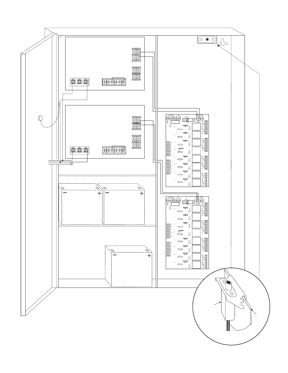
- 12 -
Maximal11D/Maximal33D/Maximal55D/Maximal77D/Maximal75D Access Power Controllers (PTC)
+
DC
---
BAT FAIL
NC C NO NC C NO
– BA
T
+
AC FAIL
Power Supply Board
L G N
–
DC
+
BAT FAIL
NC C NO NC C NO
+ BA
T
---
AC FAIL
Power Supply Board
L G N
115VAC Input
60 Hz.
Wire
Strap
(from
Enclosure
to Door)
Tamper Switch
Ground Lug
Line
Ground
Ground
Neutral
Line
Neutral
*12VDC operation: For 12VDC operation
only a single battery is needed.
Connect red battery lead
to terminal marked
[+ BAT] and to the
[positive (+)] terminal
of the battery. Connect
black battery lead to
terminal marked [BAT -]
and to the [negative (-)]
terminal of the battery.
CAUTION: Optional rechargeable stand-by batteries must
match the power supply output voltage setting.
Keep power-limited wiring separate from non power-limited.
Use minimum 0.25" spacing.
Optional Rechargeable
Stand-by Battery*
Optional Rechargeable
Stand-by Battery*
Optional Rechargeable
Stand-by Battery*
Fig. 5 - Maximal75D
Fig. 5a
Edge of
Enclosure
to Access Control Panel
or U.L. Listed
Reporting Device
Enclosure
Sentrol
model # 3012
Tamper Switch
or equivalent
(Not Included)