6 wiring plan – version ip66/ip68, 1bar, 7 switch–on phase, 7 switch-on phase – VEGA VEGAPULS 62 (≥ 2.0.0 - ≥ 4.0.0) 4 … 20 mA_HART - two-wire, approval according to LPR radio standard User Manual
Page 31
Contact pin
Colour connection
cable in the sensor
Terminal, electronics
module
Pin 1
Brown
5
Pin 2
White
6
Pin 3
Blue
7
Pin 4
Black
8
5
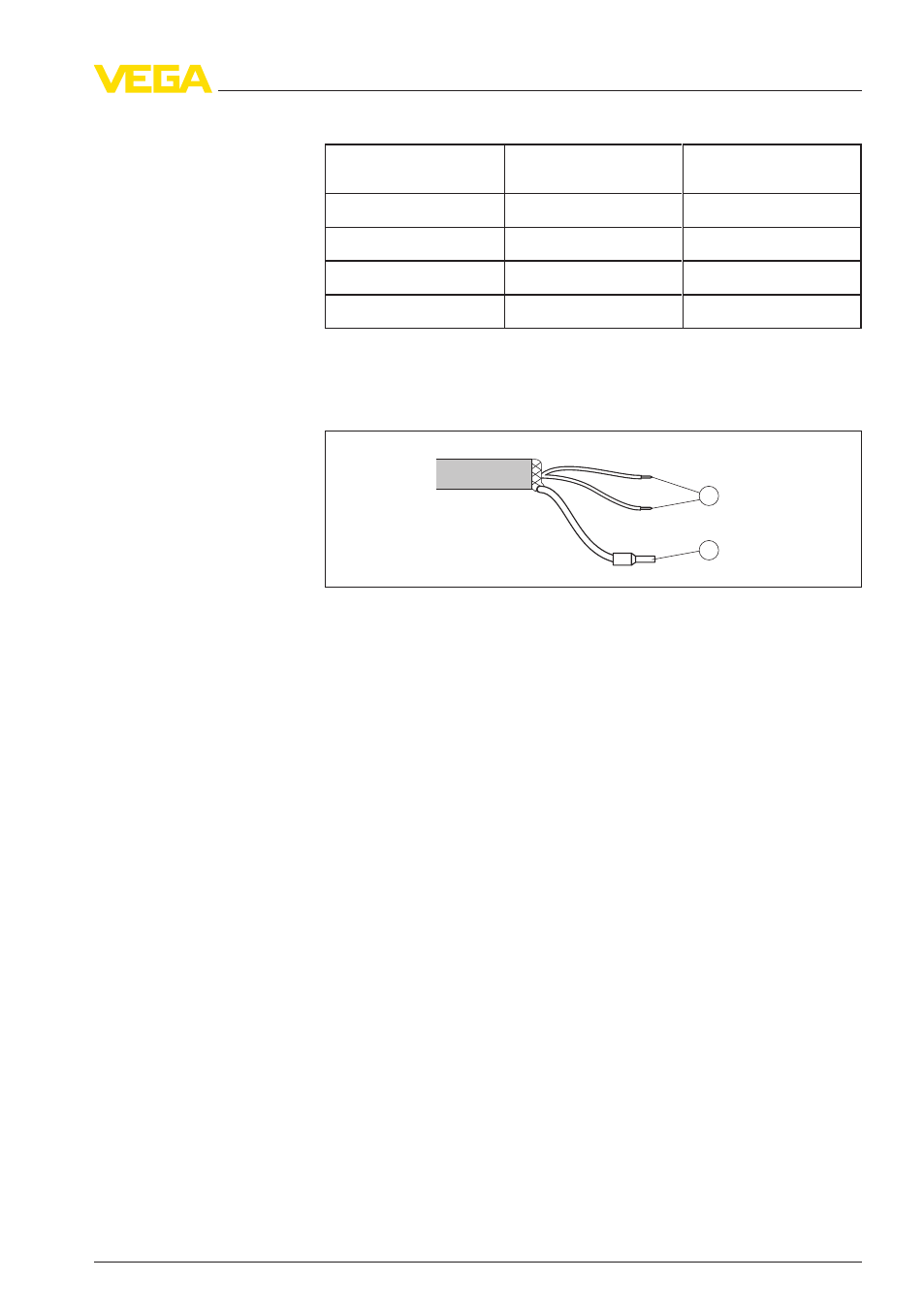
.6 Wiring plan - version IP 66/IP 68, 1 bar
1
2
Fig. 26: Wire assignment fix-connected connection cable
1
brown (+) and blue (-) to power supply or to the processing system
2
Shielding
5
.7 Switch-on phase
After connecting the instrument to power supply or after a voltage
recurrence, the instrument carries out a self-check for approx. 30 s:
l
Internal check of the electronics
l
Indication of the instrument type, hardware and software version,
measurement loop name on the display or PC
l
Indication of the status message "F 105 Determine measured
value" on the display or PC
l
The output signal jumps to the set error current
As soon as a plausible measured value is found, the corresponding
current is outputted to the signal cable. The value corresponds to the
actual level as well as the settings already carried out, e.g. factory
setting.
Wire assignment con-
nection cable
VEGAPULS
62 • 4 … 20 mA/HART - two-wire, approval according to LPR radio standard
31
5 Connecting to power supply
41718
-EN
-120301