Flange yokes, Snap ring design, J300p-2 – Spicer DRIVELINE COMPONENTS CATALOG FLANGE YOKES User Manual
Page 8
J300P-2
Flange Yokes
Snap Ring Design
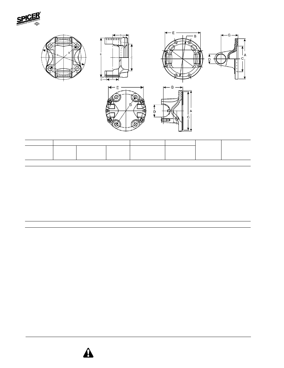
Figure 1
Figure 2
Figure 3
Important: See Safety Information in General Information Section (J300P-GI)
8
Important: See Safety Information in General Information Section (J300P-GI)
•
Part is discontinued Part is available until supply is exhausted
©
Not sold separately
A
B - Bolt Holes
C
G
Flange or
Bolt
Diameter
Number Pilot Diameter
Flange
Illustration Spicer
Swing
Circle
D-Drilled
of
M-Male
Face to
Figure
Part
Diameter
Diameter
T-Tapped
Holes
F-Female
Centerline
Number
Important: See Safety Information in General Information Section (J300P-GI)
1480 SERIES
E-4.438 D-1.375 USE KIT NO. 5-188X, 5-803X OR 5-804X
5.354
4.252
.509-D
4
2.680F
1.800
1
3-2-1769
Bolt holes are equally spaced. Part has hole thru center.
5.750
4.750
.500-D
4
3.750M
2.000
1
3-2-479
5.850
4.750
.510-D
4
2.953F
2.000
1
3-2-1869
Bolt holes are equally spaced. Part has hole thru center.
5.875
4.250
.472-T
4
2.680F
1.800
1
3-2-1719
5.875
4.750
.500-D
4
3.750M
2.000
1
3-2-609
5.875
4.750
.500-D
4
3.750M
1.500
1
3-2-489
6.875
6.125
.386-D
8
5.312M
1.938
2
3-2-909
Flange has pilot for brake
6.875
6.125
.386-D
8
6.625M
2.000
2
3-2-499
1550 SERIES
E-5.250 D-1.375 USE KIT NO. 5-155X, 5-808X OR 5-809X
4.724
3.996
.400-D
8
2.953F
3.150
1
4-2-1129
5.750
4.750
.484-D
4
3.750M
1.500
1
4-2-1149
5.750
4.750
.500-D
4
3.750M
2.000
1
4-2-819
5.760
4.724
.559-D
4
3.750M
2.000
1
5001720
5001720 was replaced by 4-2-01720
5.760
4.724
.559-D
4
3.750M
2.000
1
4-2-01720
5.774
4.750
.512-D
4
3.750M
2.000
1
4-2-669
5.875
4.750
.500-D
4
3.750F
1.500
1
4-2-759
5.875
4.750
.500-D
4
3.750M
1.500
1
4-2-679
6.156
5.250
.453-D
8
3.750F
2.500
2
4-2-829
6.412
5.500
.453-D
8
3.750F
2.500
2
4-2-849
6.875
6.125
.375-D
8
6.625M
2.000
2
4-2-689
Flange has pilot for brake
6.875
6.125
.386-D
8
5.312M
2.000
2
4-2-699
Flange has pilot for brake
6.875
6.125
.406-D
8
5.312M
2.000
2
4-2-1109
7.000
6.124
.509-D
8
3.375F
2.000
2
4-2-1159