Pinion assembly – Spicer Drive Axles Service Manual J175-S, J190-S, J210-S, J220-S, J230-SB, W230-S User Manual
Page 14
12
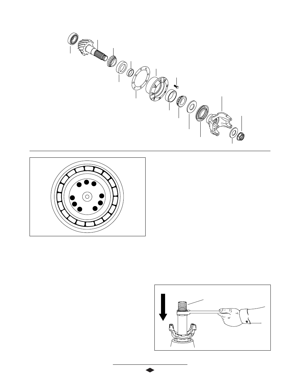
PINION ASSEMBLY
Flanged Hex Nut
(900-1,200 Lb-Ft)
(1,220-1,627 N-m)
Washer
End Yoke Assembly
Bearing Preload Spacer
Pinion Oil Seal
Outer Pinion Bearing Cup
Outer Pinion Bearing Cone
Pinion Bearing Cage Bolt
(160-180 Ft-Lb)
(217-244 N-m)
Pinion Bearing Cage
Pinion Position Shim(s)
Inner Pinion Bearing Cup
Pinion Bearing Spacer (Selective)
Inner Pinion Bearing Cone
Pinion
Pinion Pilot Bearing
7. Place pinion bearing spacer, that was removed during
disassembly, onto pinion.
8. Place pinion bearing cage onto inner pinion bearing
cone.
9. Install outer pinion bearing cone and washer on to
pinion.
10. Inspect end yoke or flange for grooves in seal
surface caused by contaminants. If grooves can
be detected with fingernail, then end yoke must be
repaired with a CR approved repair sleeve replaced.
11. Install end yoke onto pinion without seal, to allow
proper setting of bearing preload. Torque pinion nut
to 900-1200 Lb-Ft(1,220-1,627 N-m)
See Figure 7.
Figure 6
NOTE: Torque specifications, shown
on illustration, apply only to J Model.
See Page 21 for W Model torque
specifications.
1. Press inner pinion bearing cone onto pinion.
2. Press pinion pilot bearing onto nose of pinion.
3. Stake nose of pinion in 9 places, using a center
punch or equivalent tool.
See Figure 6.
4. Install inner pinion bearing cup into pinion bearing
cage.
5. Install outer pinion bearing cup into pinion bearing
cage.
6. Use a feeler gauge or shim stock (.0015 Approx.) to
ensure bearing cups are completely seated in
bearing bores. This is necessary for proper pinion
position.
Yoke Installation Tool
DST 1009
Figure 7