Troubleshooting – MSD 6520 Digital 6-Plus Ignition Control Installation User Manual
Page 7
INSTALLATION INSTRUCTIONS
7
M S D
• W W W . M S D P E R F O R M A N C E . C O M • ( 9 1 5 ) 8 5 7 - 5 2 0 0 • F A X ( 9 1 5 ) 8 5 7 - 3 3 4 4
PRESTART CHECK LIST
• The only wires connected to the coil terminals are the MSD Orange to coil positive and Black to coil negative.
• The small Red wire of the MSD is connected to a switched 12 volt source.
• Confirm the cylinder select is in the proper position for your application.
• The MSD power leads are connected directly to the battery positive and negative terminals.
• The battery is connected and fully charged if not using an alternator.
• The engine is equipped with at least one ground strap to the chassis.
TROUBLESHOOTING
Every MSD Ignition undergoes numerous quality control checks including a four hour burn-in test. If you
experience a problem with your MSD, our research has shown that the majority of problems are due to
improper installation or poor connections.
The Troubleshooting section has several checks and tests you can perform to ensure proper installation
and operation of the MSD. If you have any questions concerning your MSD, call our Customer Support
Department at (915) 855-7123, 7 - 6 mountain time.
LED
The LED on the side of the MSD monitors several operating conditions of the MSD. If the LED indicates that
there is a problem with the ignition system, follow the steps through the Troubleshooting section. The LED
will appear to be on steady at above idle speeds when everything is functioning properly.
• Flashes once per second if the battery supply voltage is low when under 3,300 rpm (while
multiple sparking). This indicates a charging problem or poor connection.
• It will flash approximately once per second if the battery input voltage is above 27 volts for
a sustained amount of time.
• The LED will flash for every trigger signal from the distributor or crank trigger. You can take
advantage of this when statically setting the timing when using the White wire to trigger.
TACH/FUEL ADAPTERS
If your tachometer does not operate correctly or if you experience a no-run situation with your foreign
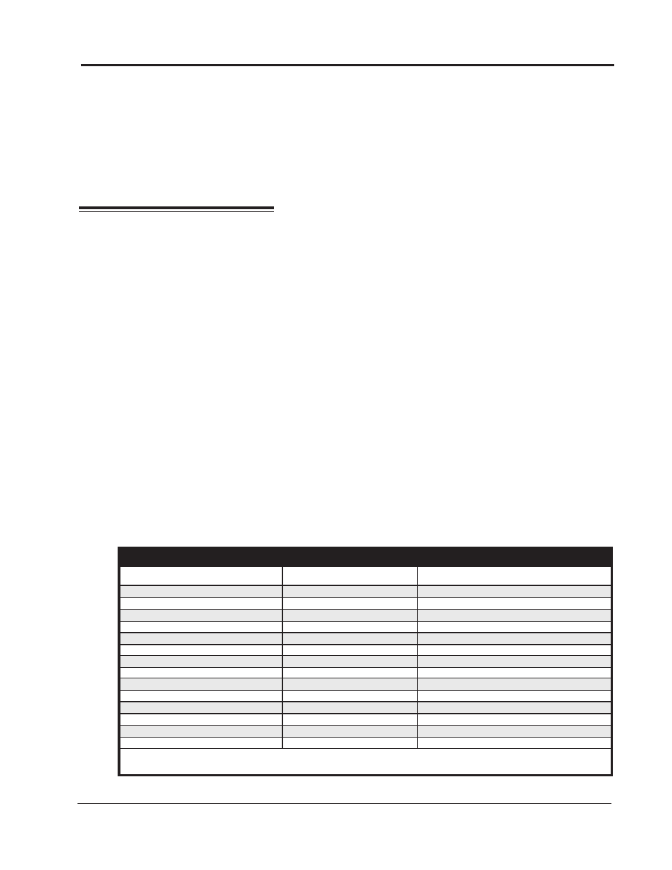
vehicle you probably need an MSD Tach Adapter. The chart in Figure 7 lists common tachometers and if
an Adapter is necessary.
Tachometer Compatibility List
AFTERMARKET TACHOMETER
WHITE WIRE TRIGGER
MAGNETIC TRIGGER CONNECTOR
AUTOGAGE
8910
8920
AUTOMETER
NONE
NONE
FORD MOTORSPORTS
NONE
NONE
MALLORY
NONE
NONE
MOROSO
NONE
NONE
STEWART (voltage triggered)
8910
8920
S.W. & BI TORX
NONE
NONE
SUN
8910
8920
VDO
NONE
NONE
AMC (JEEP)
8910
8920
CHRYSLER
8910
8920
FORD (voltage triggered)
8910
8920
GENERAL MOTORS
Bypass In-Line Filter
Bypass In-line filter
IMPORTS
8910
8920
Note: On the list above, the trigger wire on tachometers that are marked NONE may be connected to the
Tach Output Terminal on the MSD 6 Series Ignition Unit using the supplied Female Faston Receptacle.
Figure 7 Common Tachometers and Adapters.