Programming – MSD 6520 Digital 6-Plus Ignition Control Installation User Manual
Page 5
INSTALLATION INSTRUCTIONS
5
M S D
• W W W . M S D P E R F O R M A N C E . C O M • ( 9 1 5 ) 8 5 7 - 5 2 0 0 • F A X ( 9 1 5 ) 8 5 7 - 3 3 4 4
PROGRAMMING
CYLINDER SELECT
The MSD is programmed for operation
on 8-cylinder engines. If installing the
Ignition on a different style engine, the
number of cylinders will need to be
selected on the Cylinder Select Rotary
Switch (Figure 2).
START RETARD
The Start Retard will be activated during
cranking only when the Cylinder Select
dial is in the 4, 5, 6 or 7 position (Figure 2). During cranking the timing will retard 20° until 800 rpm when it
returns to the mechanical setting. If engine speed drops below 500 rpm, the start retard is activated again.
MAGNETIC PICKUP COMPENSATION
Note: If your application uses the MSD's White wire for the trigger input, the magnetic compensation circuit
is not used.
The Green wire loop of the MSD provides a timing compensation for different style trigger pickups. Having the
ability to program for the style pickup being used provides a more accurate timing signal. This compensation
is used primarily with crank trigger or locked out timing applications.
The Digital MSD is programmed at the factory for use with an MSD Crank Trigger or GM magnetic pickup.
If you are using an MSD Billet Distributor or the magnetic pickup of a Ford or Chrysler distributor the Green
Loop should be cut and sealed (Figure 3).
Note: It is recommended to check your total timing to ensure the setting for your application.
Figure 2 Programming the Number of Cylinders.
Note: Positions 8 and
9 cause the ignition
NOT to run. Use as a
theft deterrant.
Cylinder Select Cyl.Select w/ 20° Start Retard
0 = 4 cyl.
4 = 4 cyl.
1 = 6 cyl.
5 = 6 cyl.
2 = 8 cyl.
6 = 8 cyl.
3 = 6 odd
7 = 6 odd fire
Grounds: A poor ground connection can cause many frustrating problems. When a wire is specified
to go to ground, it should be connected to the battery negative terminal, engine block or chassis.
There should always be a ground strap between the engine and the chassis. Always securely connect
the ground wire to a clean, paint free metal surface.
Ballast Resistor: If your vehicle has a ballast resistor in line with the coil wiring, it is recommended
to bypass it.
Routing Wires: The MSD wires should be routed away from direct heat sources such as exhaust
manifolds and headers and any sharp edges. The trigger wires should be routed separate from the
other wires and spark plug wires. It is best if they are routed along a ground plane such as the block
or firewall which creates an electrical shield. The magnetic pickup wires should always be routed
separately and should be twisted together to help reduce extraneous interference.
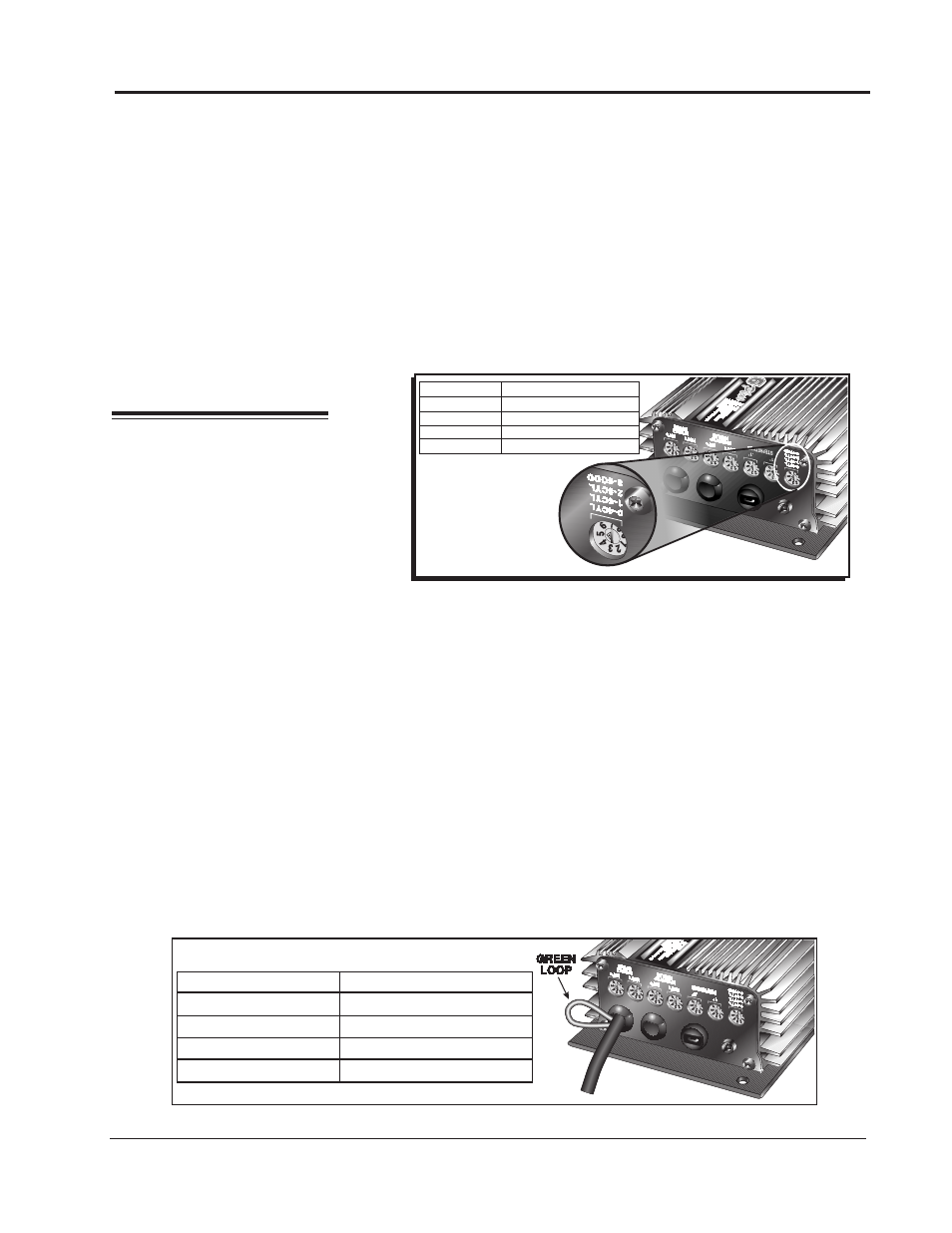
Figure 3 Programming the Compensation Circuit.
CUT LOOP
DO NOT CUT
MSD Distributors Points (Stock, Mallory, Accel)
Factory Ford
Electronic Amplifiers
Chrysler
GM HEI
MSD Crank Trigger
GREEN LOOP