MSD 6520 Digital 6-Plus Ignition Control Installation User Manual
Page 2
2
INSTALLATION INSTRUCTIONS
M S D
• W W W . M S D P E R F O R M A N C E . C O M • ( 9 1 5 ) 8 5 7 - 5 2 0 0 • F A X ( 9 1 5 ) 8 5 7 - 3 3 4 4
RETARD CONTROL
There is a single stage of retard that can be adjusted from 0 to 9.9 degrees in 1/10° increments. The retard
is activated when the Pink wire receives 12 volts which is explained on page 6.
START RETARD
To ease starting on engines with locked out timing, there is a Start Retard circuit. When set, the timing will
be retarded 20° until the engine reaches over 800 rpm. Activating the Start Retard is done with the Cylinder
Select dial and is explained on page 5.
CYLINDER SELECT
The MSD is programmed at the factory for use on 8-cylinder engines. If you are installing it to a different
engine you will have to program the Ignition. This is easily achieved through the cylinder select switch on
the side of the ignition. Page 5 outlines setting the cylinder select.
GENERAL INFORMATION
BATTERY
An MSD 6 Series Ignition Control will operate on any negative ground, 12 volt electrical system with a
distributor. The MSD can be used with 16 volt batteries and can withstand a momentary 24 volts in case of
jump starts. The Ignition will deliver full voltage with a supply of 9 - 18 volts and will operate with a supply
voltage as low as six volts.
If your application does not use an alternator, allow at least 15 amp/hour for every half hour of operation.
The MSD uses about .7 Amps for every 1,000 rpm. If the engine is cranked with the same battery or other
accessories such as an electric fuel or water pump are used, the amp/hour rating should be higher.
COILS
The MSD Digital 6 Plus Ignition can be used with most stock coils and aftermarket coils designed to replace
the stock coils. The line of MSD Blaster Coils are great for street and mild racing. For extended high rpm
operation the Blaster HVC, PN 8252, is recommended. For more information on recommended coils,
consult the supplied Coil Application Chart or check with our Customer
Service Department at (915) 855-7123.
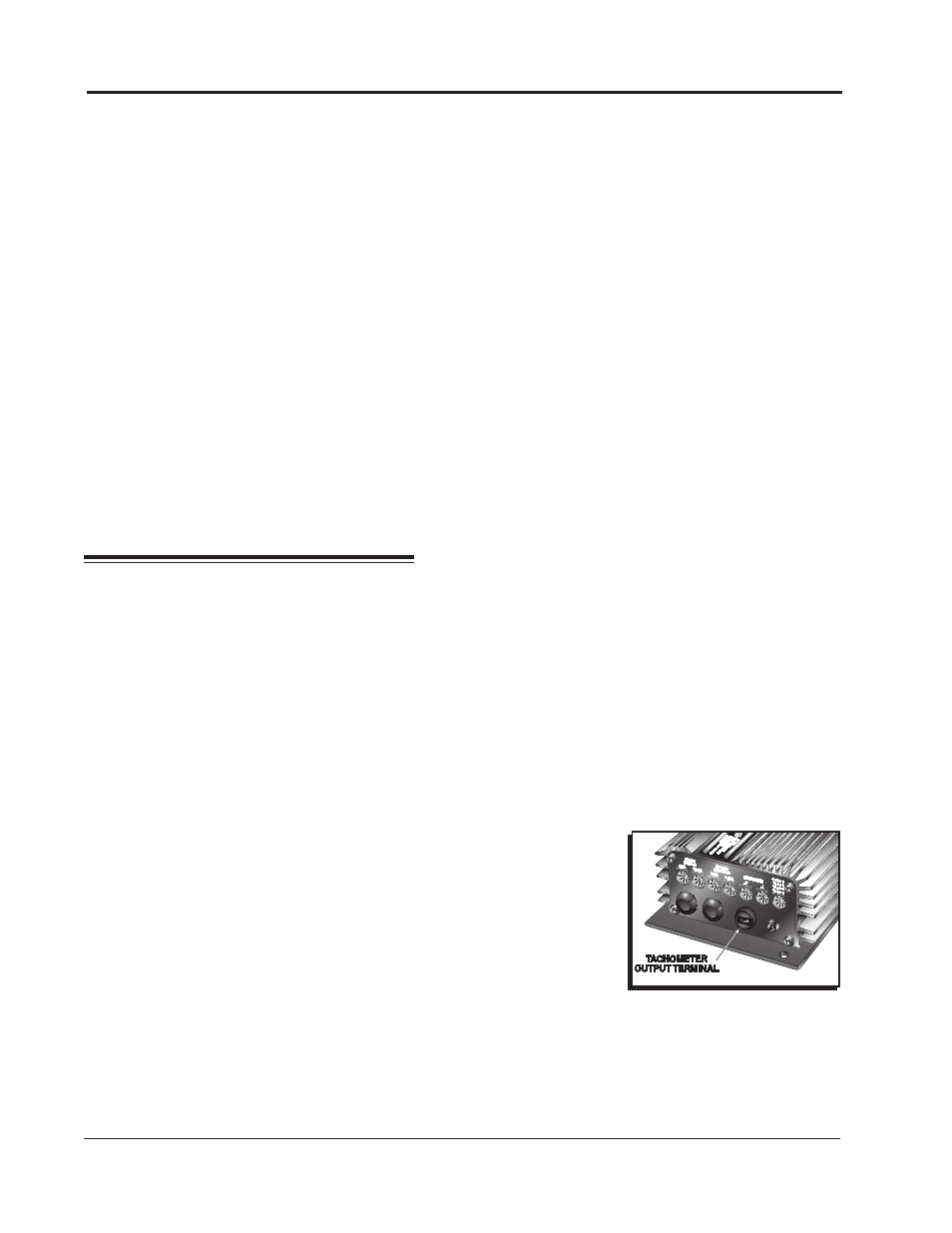
TACHOMETERS
The MSD Ignition features a Tach Output Terminal on the side of the unit
(Figure 1). This terminal provides a trigger signal for tachometers, a shift light
or other add-on rpm activated devices. The Tach Output Terminal produces
a 12 volt square wave signal with a 30° duty cycle.
Some vehicles with factory tachometers may require a Tach Adapter to
operate with the MSD. For more information on Tachometers and MSD
Tach Adapters, see the Tachometer Section on page 7.
If your GM vehicle has an inline filter it may cause the tach to drop to zero on acceleration. If this occurs,
bypass the filter.
Figure 1 Tach Terminal
PROTECTION
The MSD Digital 6 Plus has a built in reverse polarity protection circuit. This will protect the ignition in the
event of wrong connections. It will also shut off for protection from a surge in power. The ignition will still
operate once the surge or polarity is corrected.
LED INDICATOR
There is an LED that monitors the status of the Ignition. The LED monitors several parameters of the
ignition including trigger signal, low voltage and high voltage.