Wiring – MSD 62153 DIS-4 Plus High Output Installation User Manual
Page 4
4
INSTALLATION INSTRUCTIONS
M S D
• W W W . M S D P E R F O R M A N C E . C O M • ( 9 1 5 ) 8 5 7 - 5 2 0 0 • F A X ( 9 1 5 ) 8 5 7 - 3 3 4 4
WIRING
GENERAL WIRING INFORMATION
Wire Length: All of the wires of the MSD Ignition may be shortened as long as quality connectors
are used or soldered in place. To lengthen the wires, use one size bigger gauge wire (12 gauge for
the power leads and 16 gauge for all other wires) with proper connections. All connections must be
soldered and sealed.
Grounds: A poor ground connection can cause many frustrating problems. When a wire is specified to
go to ground, it should be connected to the battery negative terminal, engine block or chassis. There
should always be a ground strap between the engine and the chassis. Always securely connect the
ground wire to a clean, paint free metal surface.
ROUTING WIRES
The MSD wires should be routed away from direct heat such as the exhaust manifolds/headers and any
sharp edges. The trigger wires should be routed separate from the other wires and spark plug wires. It
is best if they are routed along a ground plane such as the block or firewall as an electrical shield.
WARNING: High Voltage is present on the coil terminals. Do not touch the coil terminals or wiring
when the engine is cranking or running.
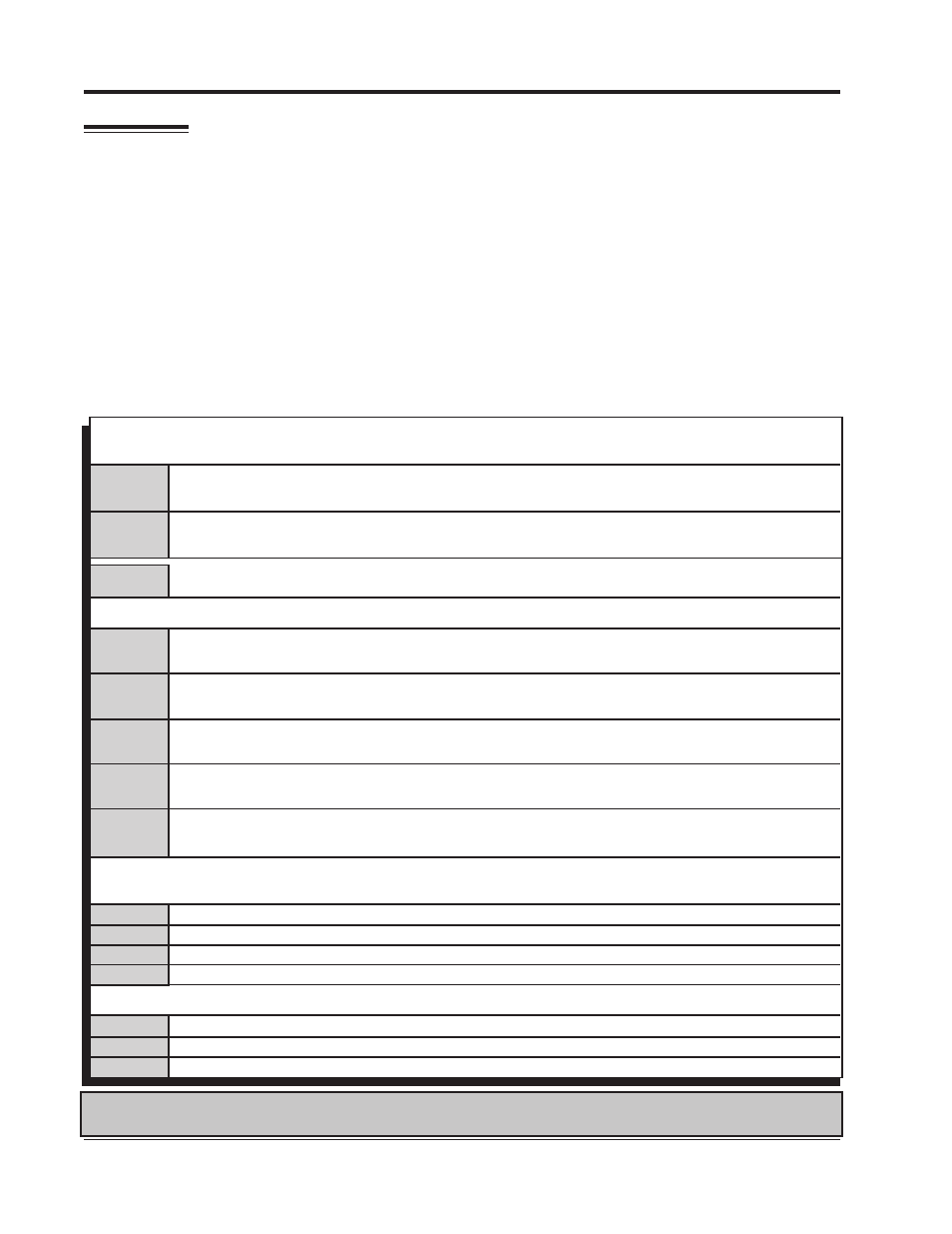
This wire connects directly to the battery positive (+) terminal, to a positive battery junction or
the positive side of the starter solenoid.
NOTE: Do not connect to alternator.
This wire connects to a good ground, either at the battery negative (-) terminal or to the engine.
Heavy
Red
Power Leads
These are the two heavy guage wires (14 guage) and are responsible for getting direct battery voltage to the ignition.
Heavy
Black
Coil Wires
Connects to a switched 12 volte source, such as the ignition key or switch.
Red
There are two Brown/Orange wires. Connects to the positive (+) terminal/wire of the coil.
NOTE: This is the only wire that makes electrical contact with coil positive (+).
Brown/
Orange
Connects to the negative (-) terminal/wire of the coil (Channel 1).
NOTE: This is the only wire that makes electrical contact with channel 1 coil negative (-).
Brown/
White
Connects to the negative (-) terminal/wire of the coil (Channel 2).
NOTE: This is the only wire that makes electrical contact with channel 2 coil negative (-).
Brown/
Green
Connects to the negative (-) terminal/wire of the coil, (Channel 3 available on DIS-4 only).
NOTE: This is the only wire that makes electrical contact with channel 3 coil negative (-).
Brown/
Yellow
Connects to the negative (-) terminal/wire of the coil, (Channel 4 available on DIS-4 only).
NOTE: This is the only wire that makes electrical contact with channel 4 coil negative (-).
Brown/
Violet
This wire is used to connect to the electronic ignition amplifier output of channel 1.
This wire is used to connect to the electronic ignition amplifier output of channel 2.
This wire is used to connect to the electronic ignition amplifier output of channel 3.
This wire is used to connect to the electronic ignition amplifier output of channel 4.
White
Green
Yellow
Violet
Trigger Wires
There are two or more circuits that can be used to trigger the MSD Ignition; from the electronic amplifier.
Brown
Blue
Pink
Ignition interrupt/theft deterrent. To activate, connect this wire to ground through a switch.
Two Step feature. To activate low rpm limit, connect this wire to 12 volts.
Step Retard. To activate the step retard connect this wire to 12 volts.
Accessory Wires