MSD 5520 Street Fire Ignition Control Installation User Manual
Page 2
2
INSTALLATION INSTRUCTIONS
S T R E E T F I R E
• W W W . S T R E E T - F I R E . C O M • ( 9 1 5 ) 8 5 7 - 5 2 0 0 • F A X ( 9 1 5 ) 8 5 7 - 3 3 4 4
MOUNTING
The Street Fire Ignition can be mounted in most positions, except directly upside down (if upside down, moisture or
water cannot escape). It can be mounted in the engine compartment as long as it is away from direct engine heat
sources. It is not recommended to mount the unit in an enclosed area such as the glove box.
When you find a suitable location to mount the unit, make sure the wires of the ignition reach their connections.
Hold the Ignition in place and mark the location of the mounting holes. Use an 1/8" drill bit to drill the holes. Use the
supplied self tapping screws to mount the box.
CYLINDER SELECT
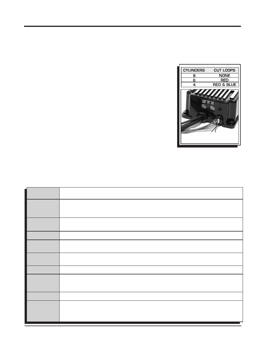
The Rev Limiter that is built into the ignition is programmed for operation on a
8-cylinder engine. If you are installing one of these units on a 4 or 6-cylinder
even-fire engine, the cylinder count must be selected. This is easily achieved
through the cylinder select wire loops on the side of the ignition. To program the
unit cut the loops as shown in Figure 1.
LED
There is a diagnostic LED next to the rpm dials. The LED will blink with each
trigger signal. It will appear On when the engine is running. If the input voltage
drops below 9 volts it will flash at idle speed. For more codes, see page 10.
WIRING
Wire Length: All of the wires of the ignition may be shortened as long as quality
connectors are used or soldered in place. To lengthen the wires, use one size
bigger gauge wire (10 gauge for the power leads and 16 gauge for the other
wires) with the proper connections.
Grounds: A poor ground connection can cause many frustrating problems.
When a wire is specified to go to ground, it should be connected to the battery negative terminal, engine block or
chassis. There should always be a ground strap between the engine and the chassis. Always securely connect the
ground wire to a clean, paint free metal surface.
These are the two heavy gauge wires (14 gauge) and are responsible for getting direct battery
voltage to the Ignition.
This wire connects directly to the battery positive (+) terminal or to a positive battery junction or
the positive side of the starter solenoid.
Note: Never connect to the alternator.
This wire connects to a good ground, either at the battery negative (-) terminal or to the
engine.
Connects to a switched 12 volt source. Such as the ignition key or switch.
Connects to the positive (+) terminal of the coil.
This is the only wire that makes electrical contact with the coil positive terminal.
Connects to the negative (-) terminal of the coil.
This is the only wire that makes electrical contact with the coil negative terminal.
Tach output wire. Connect to the tachometer or other rpm device.
There are two circuits that can be used to trigger the Street Fire Ignition; a Points circuit (White
wire) and a Magnetic Pickup circuit (Violet and Green wires). The two circuits will
never be used
together.
This wire is used to connect to the points or electronic ignition amplifier output .
These wires are routed together in one harness to form the Magnetic Pickup connector. The
connector plugs directly into an MSD Distributor. It will also connect to factory magnetic pickups
or other aftermarket pickups. The Violet wire is positive (+) and the Green is negative (-).
When
these wires are used, the White wire is not.
POWER LEADS
HEAVY RED
HEAVY BLACK
RED
ORANGE
BLACK
GRAY
TRIGGER
WIRES
WHITE
VIOLET AND
GREEN
(Magnetic
Pickup Connector)
WIRE FUNCTIONS
Figure 1 Selecting the number
of Cylinders.
CYLINDER SELECT
LOOPS