MSD 5520 Street Fire Ignition Control Installation User Manual
Page 10
10
INSTALLATION INSTRUCTIONS
S T R E E T F I R E
• W W W . S T R E E T - F I R E . C O M • ( 9 1 5 ) 8 5 7 - 5 2 0 0 • F A X ( 9 1 5 ) 8 5 7 - 3 3 4 4
ENGINE RUN-ON
If your engine continues to run even when the ignition is turned Off you are experiencing engine Run-On. This
usually only occurs on older vehicles with an external voltage regulator. Because the CDI receives power directly
from the battery, it does not require much current to keep the unit energized. If you are experiencing Run-On, it is
due to a small amount of voltage going through the charging lamp indicator and feeding the small Red wire even
if the key is turned off.
Early Ford and GM: To solve the Run-On problem, a Diode is supplied in the parts bag. By installing this Diode
in-line of the wire that goes to the Charging indicator, the voltage is kept from entering the CDI. Figure 5 shows the
proper installation for early Ford and GM vehicles.
Note: Diodes are used to allow voltage to flow only one way. Make sure the Diode is installed facing the proper
direction (as shown in Figure 5).
Ford: Install the Diode in-line to the wire going to the #1 terminal.
GM: Install the Diode in-line to the wire going to terminal #4.
GM 1973 - 1983 with Delcotron Alternators
GM Delcotron Alternators use an internal voltage regulator. Install the Diode in-line on the smallest wire exiting the
alternator (Figure 5). It is usually a Brown wire.
LED
The LED on the side of the Street Fire monitors several operating conditions of the ignition. If the LED indicates
that there is a problem with the ignition system, follow the steps through the Troubleshooting section. The LED will
appear to be on steady at above idle speeds when everything is functioning properly.
• When 12 volts are applied to the small Red wire, the LED will turn on to indicate power.
• When cranking or running, the LED will blink for each trigger signal.
• If the input voltage drops below 9 volts it will flash at idle speed.
• Code 2 will flash for low battery voltage.
• Code 3 will flash for converter off (ignition problem)
NO-RUN ON FOREIGN VEHICLES
Some foreign vehicles with fuel injection systems may require an MSD Tach/Fuel Injection Adapter to run with the
Street Fire Ignition. This is because many of these systems use the same trigger source to operate the CDI, the
tachometer and the fuel injection. This results in a voltage signal that is too low to accurately trigger the fuel injection.
To fix this, an MSD Tach Adapter, PN 8910, will remedy the problem on the majority of vehicles. If the PN 8910 does
not fix the problem, the PN 8910-EIS will be required.
Note: Toyotas and Ford Probes will require the PN 8910-EIS Adapter.
INOPERATIVE TACHOMETERS
If your tachometer fails to operate with the CDI installed you may need a Tach Adapter from MSD Ignition. Before
getting an Adapter, try connecting your tachometer trigger wire to the Gray Wire. This output produces a 12 volt, square
wave (see page 1). If the tach still does not operate, you will need a Tach Adapter. There are two Tach Adapters:
PN 8920: If you are using the Magnetic Pickup connector (Green
and Violet wires) to trigger the CDI, you will need the
PN 8920.
PN 8910: If your tachometer was triggered from the coil negative
terminal (voltage trigger) and you are using the White
wire to trigger the cdi you will need the PN 8910.
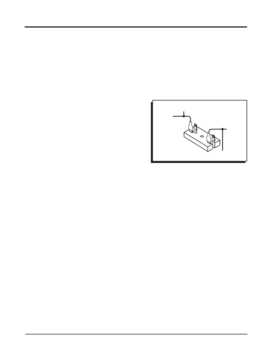
BALLAST RESISTOR
If you have a current trigger tach (originally coil positive) and
use the White wire of the CDI, you can purchase a Chrysler Dual
Ballast Resistor (used from 1973 - 1976) and wire it as shown in
Figure 4.
FROM POINTS
OR AMPLIFIER
STREET FIRE
WHITE
STREET FIRE
RED
SWITCHED 12V
(original coil+ wire from tach)
CHRYSLER DUAL
BALLAST RESISTOR
Figure 4 Wiring the Dual Ballast Resistor.