Channel assignment in xrec configurations – EVS XT3 Version 11.02 - July 2013 Configuration Manual User Manual
Page 65
•
The primary links of the V3X boards mentioned in the tables of this section correspond
to the upper connectors of a codec module.
◦
J8 for IN connectors
◦
J7 for OUT connectors (J6 is also equivalent to J7)
•
The secondary links of the V3X boards correspond to the middle connectors of a
codec module:
◦
J5 for IN connectors
◦
J3 for OUT connectors
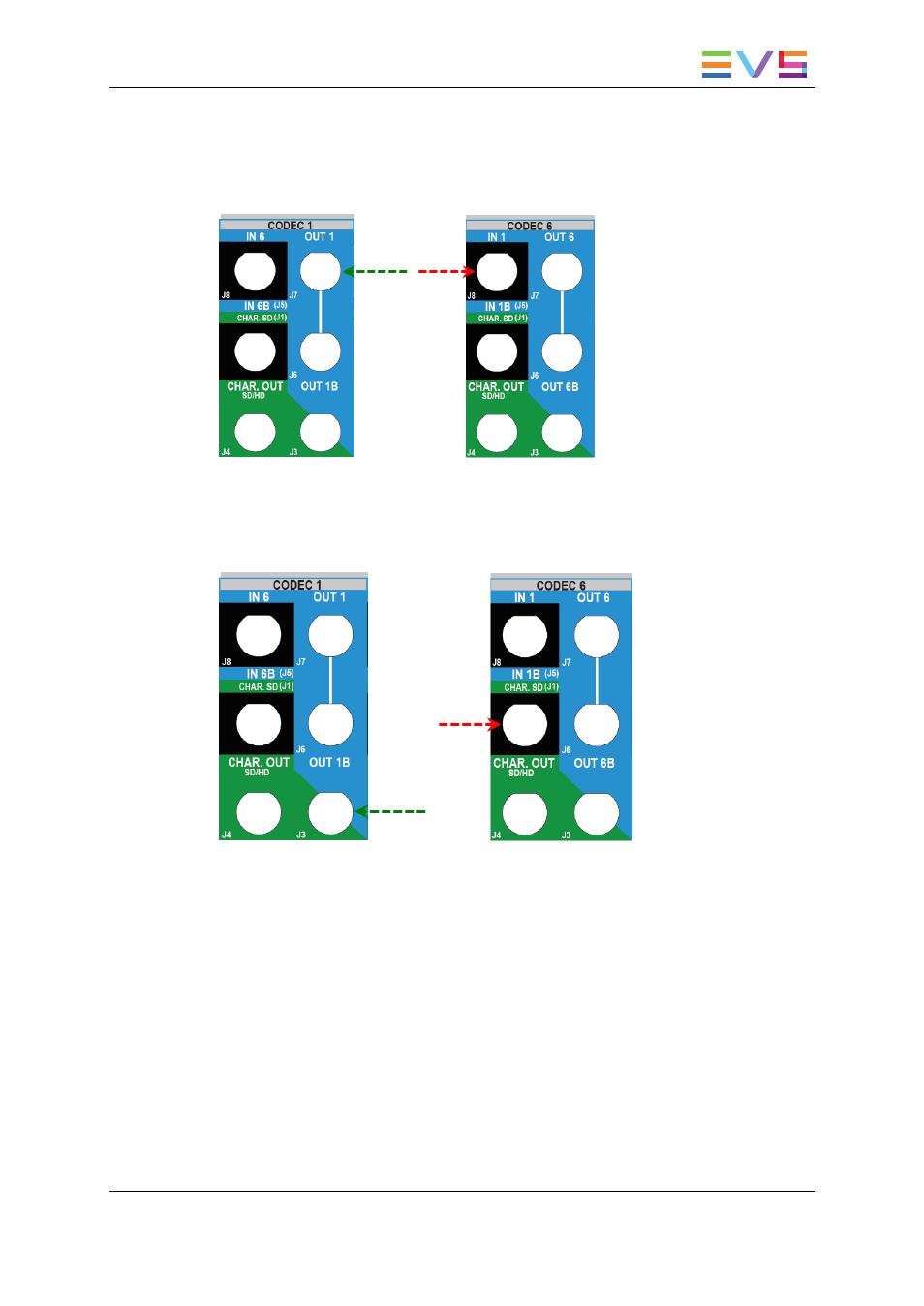
Channel Assignment in XREC Configurations
With V3X boards, the XREC configurations should be cabled in the following sequence:
1. Cable the play channels from left to right.
2. Cable the record channels from right to left starting with the primary links, without
using the left codec modules already cabled as play channels.
3. Cable the remaining record channels to assign starting from right to left, and using the
secondary link for the remaining codec modules.
CONFIGURATION MANUAL XT3 Server 11.02
3. Multicam Configuration
57
- XFReader Version 2.6 - October 2013 User Manual (44 pages)
- Xfile Version 2.14 - January 2011 User Manual (190 pages)
- MulticamLSM Version 9.00 - March 2008 User's Manual (201 pages)
- XstoreSE (4 pages)
- XEDIO Importer Version 3.1 - January 2011 User Manual (34 pages)
- Xfile Version 1.01 - December 2006 User Manual (42 pages)
- XTract Version 1.01 - January 2011 User Manual (15 pages)
- MulticamLSM Version 8.03 - Dec 2006 User's Manual (156 pages)
- IPDirector Version 6.2 - June 2013 CHANNEL EXPLORER User Manual (48 pages)
- XS Version 11.02 - July 2013 Configuration Manual (204 pages)
- GX Version 1.00 - February 2011 User’s Manual (66 pages)
- LSM Connect (32 pages)
- MulticamLSM Version 10.01 - July 2009 Operating Manual (185 pages)
- XStoreSAN (4 pages)
- XTract Installation Note (1 page)
- MulticamLSM Version 10.03 - July 2010 Configuration Manual (97 pages)
- XTAccess Version 1.18 - July 2012 User Manual (109 pages)
- XEDIO Manager Version 3.1 - January 2011 User Manual (134 pages)
- EpsioAir (2 pages)
- XSense Version 10.04 - January 2011 Operating Manual (164 pages)
- MultiReview (2 pages)
- XEDIO Media Cleaner Version 3.1 - January 2011 User Manual (16 pages)
- XEDIO Media Cleaner Version 3.1 - January 2011 User Manual (18 pages)
- XEDIO Media Cleaner Version 4.1 - December 2011 User Manual (17 pages)
- XEDIO Playout Organizer Version 4.35 - August 2013 User Manual (36 pages)
- IPDirector Version 6.0 - November 2012 Part 2 User's Manual (92 pages)
- IPWeb Version 1.0 - June 2013 User Manual (76 pages)
- XEDIO Ingest Organizer Version 3.1 - January 2011 User Manual (22 pages)
- XTnano Version 11.02 - July 2013 Operation Manual (102 pages)
- Xfile Version 2.13 - July 2010 User Manual (192 pages)
- IP2Archive Version 1.2 - October 2012 User Manual (30 pages)
- XEDIO Importer Version 4.35 - August 2013 User Manual (38 pages)
- XTract Version 1.00 - May 2010 User Manual (16 pages)
- XEDIO Browse Version 3.1 - January 2011 User Manual (38 pages)
- EPSIO Version 1.63 - May 2011 User's Manual (73 pages)
- IPDirector Version 6.0 - November 2012 Part 10 User's Manual (30 pages)
- IPDirector Version 6.2 - June 2013 IPLOGGER User Manual (74 pages)
- IPDirector Version 5.8 - July 2010 Part 7 User's Manual (229 pages)
- XFLY Streamer Version 1.02 - April 2013 User Manual (25 pages)
- OpenCube MXFTK Version 2.6 - October 2013 User Manual (42 pages)
- IPDirector Version 4.3 - October 2007 Part 3 User's Manual (204 pages)
- IP2Archive Deep Archive Sync Version 1.1 - October 2012 User Manual (66 pages)
- XEDIO Playout Organizer Version 3.1 - January 2011 User Manual (29 pages)
- MulticamLSM Version 10.04 - January 2011 Configuration Manual (98 pages)
- XTAccess Version 1.19 - November 2012 User Manual (112 pages)