Bosch GFF 22 A Professional User Manual
Page 17
English | 17
Bosch Power Tools
1 609 929 N81 | (18.5.11)
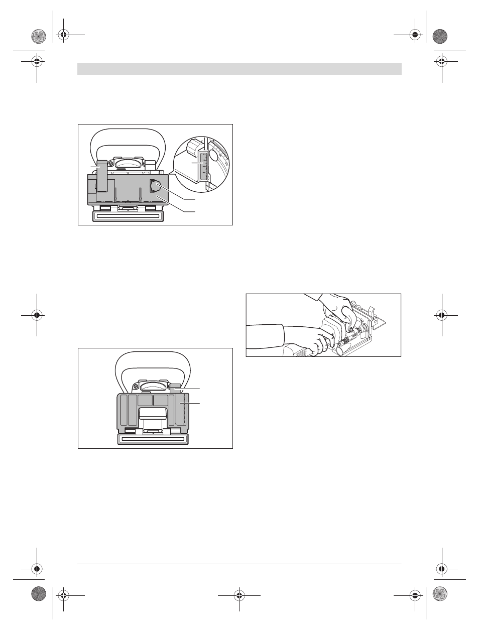
To mount the adjustable height stop 9, place it on the angle
stop 17 and screw it into the guide on the angle stop with
knob 8.
Note: Do not exert any force when mounting! The stop 9
slides in easily when in the correct position.
With the knob 8, set the desired distance on the height scale
4. Then retighten the clamping lever 12.
In order to position the groove centred in the workpiece, the
adjustable height stop must be set to half of the workpiece
thickness.
Example: For an 18 mm thick workpiece, set the height scale
to 9 mm.
To remove the adjustable height stop 9, loosen clamping lever
12. With knob 8, unscrew the height stop upward out of the
angle stop 17.
Setting the Cutting Angle
The angle stop 17 enables easy cutting of grooves on mitre
joints.
To adjust the angle stop 17, loosen clamping lever 3. Pivot the
angle stop until the desired angle is set on the angle scale 5
(latching points are located at 0°, 45° and 90°). Then tighten
clamping lever 3 again.
f
After adjusting the cutting angle, pay attention that
neither the adjustable height 9 stop nor the die attach-
ment plate 16 are in the path of the cutting disc. Check
as follows: With the machine switched off, simulate a cut
and push the cutter outlet e.g., against a table edge until
the cutting disc becomes visible. The cutting disc, when
driven out to the maximum position, may not touch the ad-
justable height stop 9 or the attachment plate 16.
Starting Operation
f
Observe correct mains voltage! The voltage of the pow-
er source must agree with the voltage specified on the
nameplate of the machine. Power tools marked with
230 V can also be operated with 220 V.
f
The machine may be switched on only when the base
plate 33 is locked securely with the clamping screw 32
and the lock washer 31.
f
Before switching on, check if the automatic returning ac-
tion of the motor unit functions properly. Push the cutter
outlet e.g., against a table edge until the cutting disc be-
comes visible. When the pressure is released, the cutting
disc must be completely pulled back into the base plate.
Switching On and Off
To switch on the machine, push the On/Off switch 2 forward
and press it down at the front to lock on.
To switch off the machine, press down the On/Off switch 2 at
the rear so that the switch springs back to the off position.
Working Advice
f
When working with the machine, always hold it firmly
with both hands and provide for a secure stance. The
power tool is guided more secure with both hands.
f
Keep your hands away from the cutting area and the
cutting disc.
While working, hold handle 1 with one hand and auxiliary han-
dle 15 with the other hand.
f
Apply the machine to the workpiece only when
switched on. Otherwise there is danger of kickback when
the cutting tool jams in the workpiece.
Carry out the routing process applying uniform feed.
Establishing the Cutting Position
The vertical centre mark of cut 11 on the angle and height
stop indicates the centre of the cut (vertical to the cutting
disc). The maximum width of the cut is indicated by the two
marks 10 on the adjustable height stop 9.
For positioning of the height, the horizontal centre mark of cut
6 on the base plate, which indicates the horizontal centre of
the cutting disc, is helpful.
The direction-of-rotation arrow 13 on the housing of the
power tool indicates the rotation direction of the cutting disc.
Cutting Groove Joints
Examples for the following groove joints are shown on the
graphic pages:
– Corner joints: With the angle stop, see figure C; with the
adjustable height stop, see figure D
– Mitre joints: With the angle stop, see figure E; with the ad-
justable height stop, see figure F
12
4
8
9
3
17
OBJ_BUCH-268-003.book Page 17 Wednesday, May 18, 2011 11:03 AM