Operation – Bosch GFF 22 A Professional User Manual
Page 16
16 | English
1 609 929 N81 | (18.5.11)
Bosch Power Tools
– Loosen the clamping screw 32 by approx. 3 turns.
Note: Do not completely unscrew the clamping screw 32
so that the lock washer 31 is not lost. Without the lock
washer, the base plate 33 cannot be secured.
– Pivot the base plate 33 upward. Hold the machine in such
a manner that the base plate will not pivot back.
– Press the spindle lock button 14 and keep it pressed.
– Loosen and remove the clamping nut 24 with the two-pin
spanner 23 provided.
– Remove the cutting disc 25 if mounted, and clean it.
– Remove the mounting flange 28 if mounted, and clean it.
– Place the mounting flange 28 onto the cutter spindle 29 in
such a manner that the centring collar 27 (22 mm diame-
ter) faces upward. The flats of the mounting flange must
engage onto the flats of the cutter spindle (anti-twist pro-
tection).
– Place the clean cutting disc 25 as shown in the figure onto
the mounting flange 28 in such a manner that the direction-
of-rotation arrow on the cutting disc 26 is visible and corre-
sponds with the direction-of-rotation arrow of the cutter
spindle 30. The mounting bore of the cutting disc must
engage in the centring collar 27 of the mounting flange.
– Screw the clamping nut 24 onto the cutter spindle 29.
With the spindle lock button 14 pressed, firmly tighten the
clamping nut with the two-pin spanner 23.
f
Check if the cutting disc is properly mounted and ro-
tates freely.
– Pivot the base plate 33 down. Pay attention that the lock
washer 31 rests on the base plate (with the clamping screw
32 alone the base plate cannot be fastened securely).
– Tighten the clamping screw 32.
f
Check if the base plate 33 is locked securely.
Dust/Chip Extraction
f
Dusts from materials such as lead-containing coatings,
some wood types, minerals and metal can be harmful to
one’s health. Touching or breathing-in the dusts can cause
allergic reactions and/or lead to respiratory infections of
the user or bystanders.
Certain dusts, such as oak or beech dust, are considered
as carcinogenic, especially in connection with wood-treat-
ment additives (chromate, wood preservative). Materials
containing asbestos may only be worked by specialists.
– As far as possible, use a dust extraction system suitable
for the material.
– Provide for good ventilation of the working place.
– It is recommended to wear a P2 filter-class respirator.
Observe the relevant regulations in your country for the
materials to be worked.
Clean the vacuum connection 21, if required. For this, pivot
up the base plate 33 (see “Installing/Replacing the Cutting
Disc”, page 15) and pull off the vacuum connection.
External Dust Extraction (see Accessory Page)
Insert the extraction adapter (accessory) with a light turning
motion into the vacuum connection 21. Insert the sleeve of a
vacuum hose (accessory) with a turning motion into the extrac-
tion adapter. Connect the vacuum hose to a vacuum cleaner.
The vacuum cleaner must be suitable for the material being
worked.
When vacuuming dry dust that is especially detrimental to
health or carcinogenic, use a special vacuum cleaner.
Internal Dust Extraction with Dust Bag
(see Accessory Page)
For small cutting jobs, the dust bag 22 can be used.
Insert the sleeve of the dust bag 22 with a light turning motion
into the vacuum connection 21.
To maintain optimum dust collection, empty the dust bag 22
in good time.
For this, pull off the dust bag 22, open the zipper and empty
the dust bag.
Operation
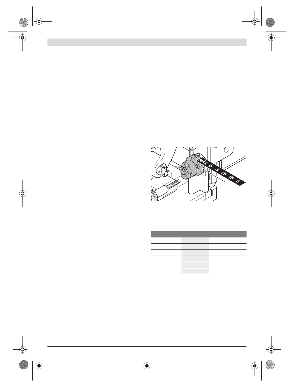
Adjusting the Depth-of-cut
With the cutting depth adjustment knob 18, the depth-of-cut
can be set. The cutting depth adjustment knob has set stops
for six biscuit dowel sizes.
Correlation of the set stops to biscuit dowel sizes and depths-
of-cut:
When using resharpened cutting discs, the depth-of-cut may
possibly need to be readjusted. For this, loosen the lock nut
19. The depth-of-cut can be reduced by turning the knurled
screw 20 in clockwise direction or increased by turning in an-
ticlockwise direction. Check the adjusted cutting depth by
carrying out trial cuts. Afterwards, firmly tighten the lock nut
19 again.
Setting the Adjustable Height Stop
With the adjustable height stop 9, the distance between the
upper surface of the workpiece and the intended groove can
be set.
Set stop
Biscuit dowel
Depth-of-cut in mm
0
No. 0
8
10
No. 10
10
20
No. 20
12.3
S
Simplex
13
D
Duplex
14.7
MAX
–
22
18
OBJ_BUCH-268-003.book Page 16 Wednesday, May 18, 2011 11:03 AM