ACU-RITE ENC 250SS User Manual
Page 11
Acu-Rite Companies Inc.
ENC 250™
SINGLE SECTION
9
Encoder Installation Procedure
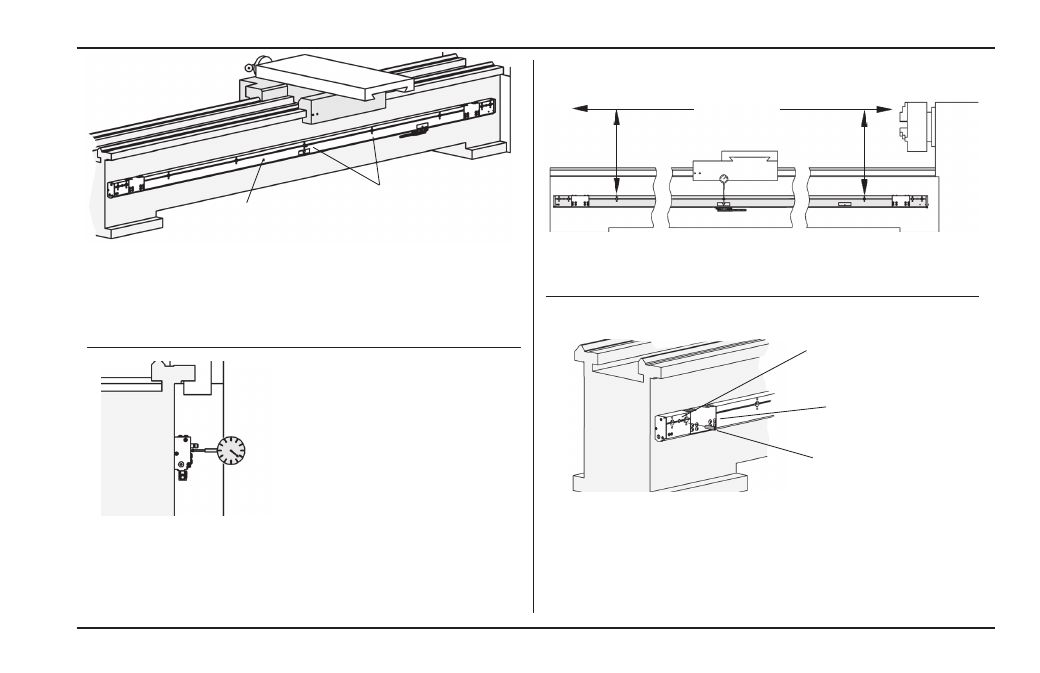
• Loosen the next two fasteners to the right of the high point.
• Move indicator to the first hole location, insert two M3 x 25mm
SHSS (leveling set screws).
• Use the leveling screws to align the face to within [.012”] .3mm
to the high point along the axis travel and secure the fastener.
Example:
high point
Loosen next two
fasteners
• Move indicator to the next hole location, and loosen the next
fastener to the right of that fastener. Align this location.
• Repeat the previous steps to align the face at each fastener.
• Return to the high point, and use the same procedure working to
the left end.
Run indicator along the front
face to align scale case to within
[.012”] .3mm to the axis travel
• Recheck the scale case top alignment, by starting at the
center hole location, and adjust as necessary.
Axis Travel
Align to within [.012”] .3mm TIR to the axis
travel measuring over each hole location
Dowel pin anchoring ...
• Drill a [.302”] 7.7mm diameter hole through the dowel pin hole
locations at each end of the scale case [.375] 9.5mm deep.
• Use a [.312] 8mm reamer to provide a press fit.
• Insert the dowel pins at each end, with the threaded holes facing
outward.
• Loosen the BHCS (16) on each expansion cover, approximately
[1/8”] 3mm turn each.
[5/16”] 8mm Dowel
Pin (2)
Scale case holes are
undersized to insure
accurate centering.
BHCS (16) on each
expansion cover