ACU-RITE ENC 250SS User Manual
Page 10
Acu-Rite Companies Inc.
ENC 250™
SINGLE SECTION
8
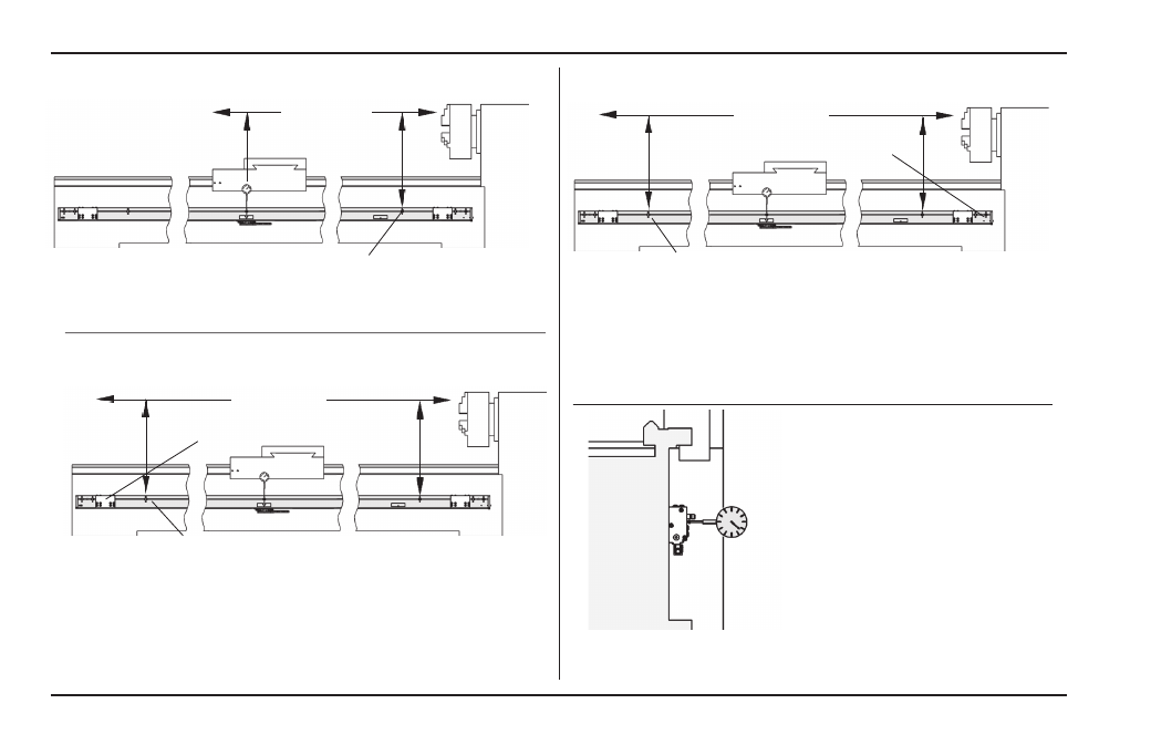
Encoder Installation Procedure
• Align the furthest left mounting hole before the expansion
cover with the furthest right attached hole.
• Transfer punch the left hole location.
• Drill / tap location for a [1/4-20 x 1/2”] M6 x 12mm deep.
• Attach the left end, and align the top of the scale case.
Secure the fastener.
Axis Travel
• Attach and align the top of the scale case. Secure the
fastener.
Align to within [.012”] .3mm TIR to the axis
travel measuring over each hole location
Axis Travel
Align to within [.012”] .3mm TIR to the axis
travel measuring over each hole location
Left expansion cover
[1/4-20 x 1-1/4”] M6 x 30mm SHCS & M6 flat washer
• Align the front face of the scale case to within [.012”] .3mm
TIR of the axis travel following the next steps.
Run an indicator along the front
face to locate the high point.
Mark the location, and set the
indicator to 0.000”
• Starting at the right end, align the top of the scale case,
and transfer punch each remaining hole location.
• Remove scale, drill / tap locations for a [1/4-20 x 1/2”]
M6 x 12mm deep.
• Attach the scale case, align to within [.012”] .3mm TIR, &
secure all fasteners. Note: Replace stud with fastener.
Axis Travel
Align to within [.012”] .3mm TIR to the axis
travel measuring over each hole location
[1/4-20 x 1-1/4”] M6 x 30mm SHCS & M6 flat washer
Starting hole
[1/4-20 x 1-1/4”] M6 x 30mm SHCS & M6 flat washer