ACU-RITE SENC 150 User Manual
Page 6
4
Mounting Information
SENC 150
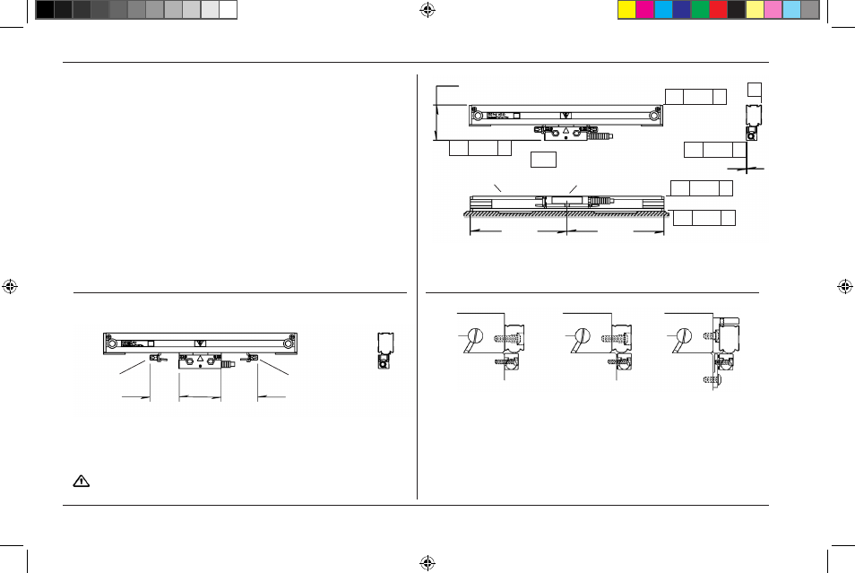
Use this information to plan your linear encoder installation.
• Mount the linear encoders close to machine guide ways to
ensure system accuracy.
• One side of the linear encoder addresses flush mounting
surfaces, and the opposite side addresses offset mounting
surfaces.
• If space between the reading head and the mounting surface
exceeds .18”, use a spacer or mounting bracket to reduce
space.
• ACU-RITE
®
bracket kit instructions provide step by step
installation procedures.
• Tolerances of .010” TIR apply to all mounting dimensions.
• Center support mounting surface required for 24” through 60”
linear encoder measuring lengths mounted without a spar.
• Allow clearance for alignment bracket removal.
• Alignment brackets must not be removed until instructed.
• Use reading head leveling set screws when surfaces are not
flush.
• Reading head bracket required for a space >.18”.
Flush
mounting
offset
mounting
Backup spar
mounting
Move bracket past
the cable strain relief
Alignment bracket removal clearance
1.0
[25mm]
1.38
[35mm]
Alignment
bracket
Alignment
bracket
Scale case
-A- = Machine Travel
Reading head
Equal
Equal
1.876 .010 [47.6]
0.0 ± .010
// .010 A
// .010 A
// .010 B
// .010 A
// .010 A
B
ACU-RITE
®
516291-21_Ve00_SENC_150.indd 6
10/22/2009 10:00:39 AM