ACU-RITE SENC 150 User Manual
Page 12
Encoder Installation Procedure
SENC 150
These steps apply to all encoder mounting conditions, if a spar is
being used, go to “Spar Installation Procedure” on page 11.
• ACU-RITE
®
bracket kit instructions supercede this section.
• Adjust drill depths and fastener lengths as required.
• When instructed on page 10: Adjust the leveling set screws as
follows:
1. Insert, but do not tighten 8-32 (M4) reading head screws.
2. Place a .001”-.003” shim between the leveling set screws
and mounting surface.
3. Adjust each set screw until a slight drag is felt on the shim.
4. Evenly tighten the 8-32 (M4) reading head mounting screws.
• Contact your Authorized Distributor should you require
additional assistance.
• Align the center marks on the reading head and scale assembly
by sliding the reading head and brackets along the case.
• Locate the scale case so underside of end caps are flush with
the axis parting line.
• Mark one end mounting hole location.
• Move the machine axis to its center of travel.
• Mark the axis for quick return to center.
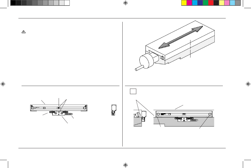
• Configure the encoder cable exit direction (see page 3).
Scale case
Reading head assembly
Alignment
brackets (2)
CL
Align top of scale case to
within .015” of -A-
-A- = Axis travel
Cable assembly
End cap
Scale case
Axis parting line
End mounting hole (typical)
Center marks
Center mounting axis
Mark center of travel
CL
10
ACU-RITE
®
516291-21_Ve00_SENC_150.indd 12
10/22/2009 10:00:43 AM