ACU-RITE SENC 150 User Manual
Page 13
SENC 150
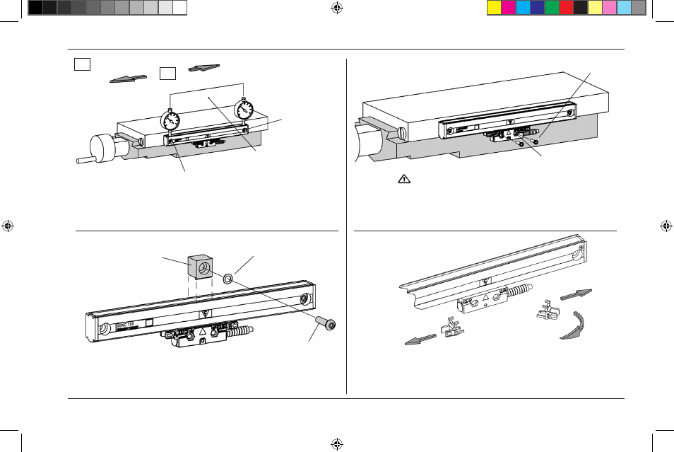
Encoder Installation Procedure
• Drill / tap the first end mounting hole / attach the linear encoder.
• Align to within .010” TIR. to -A-, drill / tap second end hole.
• Attach the linear encoder / align to within .010” TIR. to -A-.
• Center the axis and mark the reading head mounting holes.
• Move axis, drill / tap holes for 8-32 (M4).
• Attach head to axis / Set leveling screws / Secure fasteners.
• Use the center support(s) when provided.
• Place supports at equal intervals along the encoder’s length.
Center support
1/4-20 x 1” BHCS & Scale flat washer (M6 x 25mm)
Align to within .010” TIR to -A-
Drill / tap
for 1/4-20 (M6).
8-32 x 3/4” SHCS
(M4 x 20mm)
Drill / tap for 8-32 (M4)
1/4-20 x 3/4” SHCS
(M4 x 20mm)
-A- = Axis travel
-A-
Flat washer (M6)
Do not tighten prior to adjusting leveling set screws
• Slide the brackets away from the reading head.
• Remove the alignment brackets and save for future use.
• Proceed to page 13, “Checking Your Installation”.
Alignment bracket
removal
Slide brackets away from reading head and cable.
Twist 45°
11
ACU-RITE
®
516291-21_Ve00_SENC_150.indd 13
10/22/2009 10:00:44 AM