6 sas controller rear view, A12-ss, A12r-ss – Accusys ExaRAID A24U-SS User Manual
Page 19: A12r-ss a12u-ss, Product overview
Product Overview
12
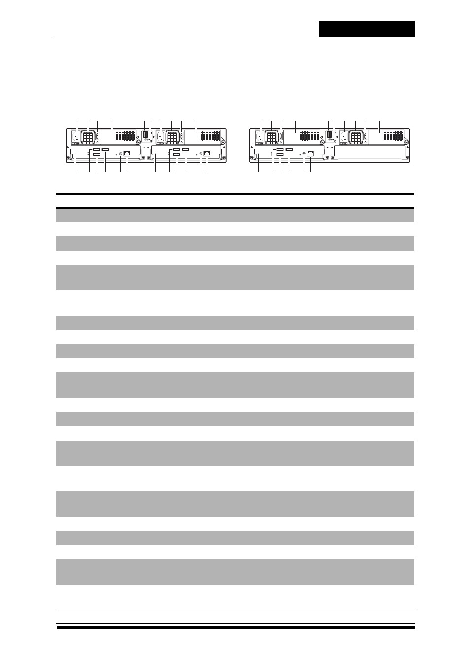
1.6 SAS Controller Rear View
A12-SS
No. Item
Description
1
AC power port
Connects to the power source.
2
Power supply handle
Use to pull out the power supply.
3
Power supply switch
Use to switch the power on or off.
4
Cooling fan 1
System cooling fan.
5
Chassis ID
Use for JBOD enclosure only. See 1.7
6
UPS port
Provides UPS powered data
connection.
7
AC power port
Connects to the power source.
8
Power supply handle
Use to pull out the power supply.
9
Power supply switch
Use to switch the power on or off.
10
Cooling fan 2
System cooling fan.
11
Controller A
RAID system controller A (Primary
controller),
12
Host channel 2 (Controller A)
Connects to the host server.
13
Expansion port (Controller A)
Use for JBOD expansion. (A12R-SJ)
14
Host channel 1 (Controller A)
Connects to the host server.
15
RS-232 port
Connects to external terminal for CLI
management.
16
Ethernet port
Connects to LAN for GUI
management.
17
Controller B
RAID system controller B (Secondary
controller).
18
Host channel 2 (Controller B)
Connects to the host server.
19
Expansion port (Controller B)
Use for JBOD expansion. (A12R-SJ)
20
Host channel 1 (Controller B)
Connects to the host server.
21
RS-232 port
Connects to external terminal for CLI
management.
22
Ethernet port
Connects to LAN for GUI
management.
A
1
B
2
15
ON
DIP
4
3
2
U
P
S
COM LAN
CH 2
EXP
EXP Access
EXP Link
CTRL Ready
CH 1
COM LAN
CH 2
EXP
EXP Access
EXP Link
CTRL Ready
CH 1
1
13
12
14
15 16
11
2 3
4
7
5 6
19
18
20
21 22
17
8 9
10
A
1
B
2
15
ON
DIP
4
3
2
U
P
S
COM LAN
CH 2
EXP
EXP Access
EXP Link
CTRL Ready
CH 1
1
13
12
14
15 16
11
2 3
4
7
5 6
8 9
10
A12R-SS
A12U-SS