Application data (continued) – York YR User Manual
Page 22
22
YORK INTERNATIONAL
FORM 160.81-EG1
Application Data (continued)
In addition, the ASHRAE Standard 15 requires a refriger-
ant vapor detector to be employed for all refrigerants. It is
to be located in area where refrigerant from a leak would
be likely to concentrate. An alarm is to be activated and
the mechanical ventilation started at a value no greater
than the TLV (Threshold Limit Value) of the refrigerant.
ELECTRICAL CONSIDERATIONS
Motor Voltage – Low voltage motors (200 - 600 volts)
are furnished with six leads. Motor circuit conductor size
must be in accordance with the National Electrical Code
(NEC), or other applicable codes, for the motor full-
load amperes (FLA). Flexible conduit should be used
for the last several feet to the chiller in order to provide
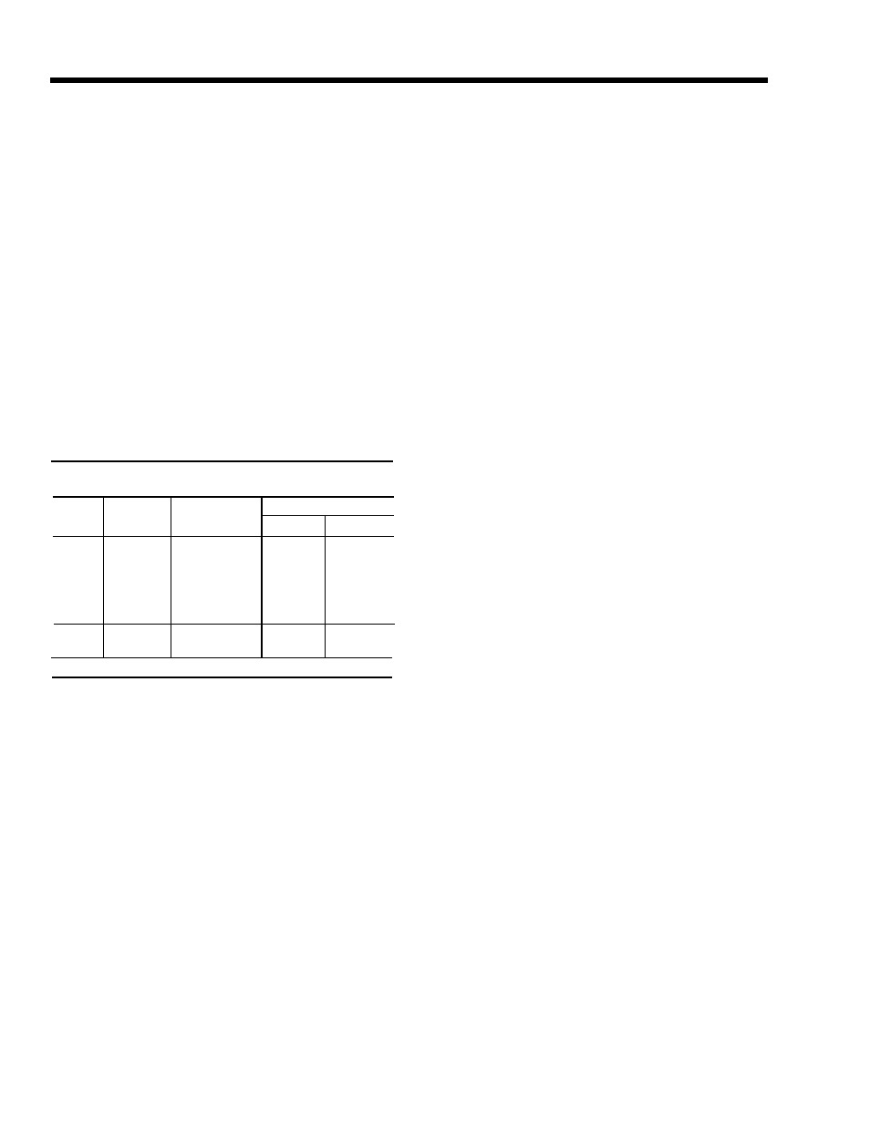
vibration isolation. Table 2 lists the allowable variation
in voltage supplied to the chiller motor. The unit name-
plate is stamped with the specific motor voltage and fre-
quency for the appropriate motor.
Power Factor Correction Capacitors – Capacitors can
be applied to a chiller for the purpose of power factor
correction. For remote-Mounted Electro-Mechanical
Starters, the capacitors should be located on the load
side of the starter. For YORK SSS, the capacitors must
be located on the line side of the starter. The capacitors
must be sized and installed to meet the National Elec-
trical Code (NEC) and be verified by YORK.
Ampacity on Load Side of Starter – Electrical power
wire size to the chiller is based on the minimum unit
ampacity. For YORK SSS, this wiring is done at the
factory. For remote starters, the National Electrical Code
defines the calculation of ampacity, as summarized be-
low. More specific information on actual amperage rat-
ings will be supplied with the submittal drawings.
• Six-lead type of starting (Star-Delta)
Minimum circuit ampacity per conductor (1 of 6):
Ampacity = .721 x compressor motor amps.
• Three-lead type of starting
(Across-the-Line, Autotransformer and
Primary Reactor)
Minimum circuit ampacity per conductor (1 of 3):
Ampacity = 1.25 x compressor motor amps.
Ampacity on Line Side of Starter –
The only additional load on the circuit for the chiller
would be the control transformer, unless it is supplied
by a separate source.
125% of compr.
+
FLA of all other
Min. Circuit Ampacity =
motor amps loads on the circuit
Branch Circuit Overcurrent Protection – The branch
circuit overcurrent protection device(s) should be a time-
delay type, with a minimum rating equal to the next stan-
dard fuse/breaker rating above the calculated value. It is
calculated taking into account the compressor motor
amps and may also include control transformer. Refer
to submittal drawings for the specific calculations for each
application.
MOTOR ELECTRICAL DATA
The full-load amperes (FLA) listed in Tables 3 and 4
are maximum values and correspond to the maximum
motor kW listed. When the Input power (kW) is less
than maximum motor kW, the FLA should be reduced
using the following equation:
Starters – The chiller is available with a factory-mounted
and wired YORK Solid State Starter for 200 - 600 volt
applications. Other types of remote mounted starters
are available. These electro-mechanical starters must
be furnished in accordance with YORK Standard R-
1131. Specification. This will ensure that starter com-
ponents, controls, circuits, and terminal markings will
be suitable for required overall system performance.
Controls – A 115 volt, single phase, 60 or 50 Hertz
(4.5 kVa) power supply must be furnished to the chiller
from a separate, fused disconnect or from a control
transformer included as an option with electro-mechani-
cal starters. No field control wiring is required, when
the YORK SSS is supplied.
Copper Conductors – Only copper conductors should
be connected to compressor motors and starters. Alu-
minum conductors have proven to be unsatisfactory
when connected to copper lugs. Aluminum oxide and
the difference in thermal conductivity between copper
and aluminum cannot guarantee the required tight con-
nection over a long period of time.
TABLE 2 – MOTOR VOLTAGE VARIATIONS
200
200/208
180
220
230
220/240
208
254
380
380
342
415
460
440/460/480
414
508
575
575/600
520
635
380
380/400
342
423
415
415
374
440
60 HZ
50 HZ
FREQ.
RATED
VOLTAGE
NAMEPLATE
VOLTAGE
MIN.
MAX.
OPERATING VOLTAGE