Chapter 1 install and wire the series 733/734, Chapter 1, Install and wire the series 733/734 – Watlow Series 733 Service User Manual
Page 3: Dimensions, Panel cutout, Install, Series 734, Series 733 panel cutout
3
WATLOW Series 733/734 Service Manual
Install & Wire, Chapter 1
Install
Chapter 1
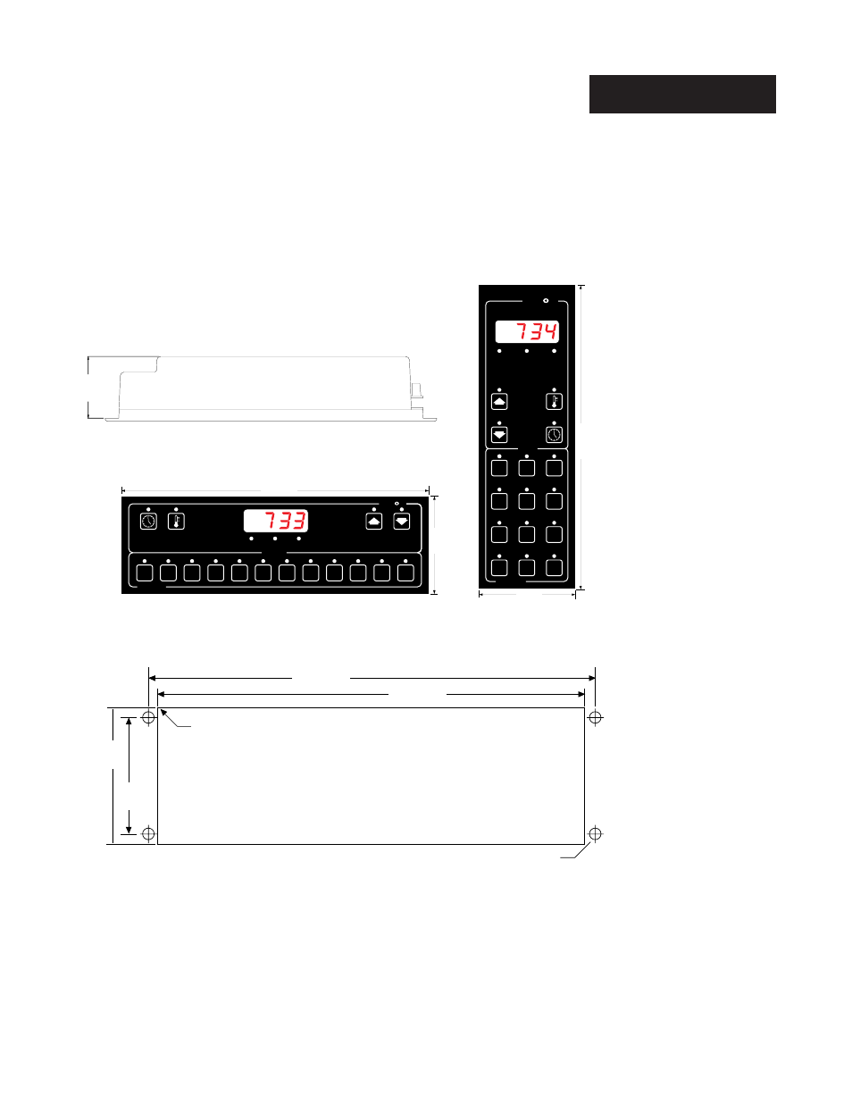
Install and Wire the Series 733/734
Front panel mounting for ease of installation and service.
Series 734
Figure 1 -
Series 733 and 734
Dimensions.
˜
NOTE:
For Series 734
orientation (verti-
cal), rotate the panel
cutout 90°.
Figure 2 -
Panel Cutout.
1.975
(50 mm)
Series 733
Panel Cutout
˜
SERIES 733
TL
W
WA
8
10
12
1
3
5
2
4
6
7
9
11
EVENT
LOAD 1
READY
MENUS
10.625"
(270 mm)
3.25"
(83 mm)
SERIES 734
1
10
7
4
2
11
8
5
3
12
9
6
EVENT
READY
LOAD 1
MENUS
TL
W
WA
10.625"
(270 mm)
3.25"
(83 mm)
9.78"
(248 mm)
3.13"
(80 mm)
0.27" Dia.
(7 mm)
2.75"
(70 mm)
Use four #6-32 screws
with nutserts
(customer supplied)
10.13"
(257 mm)
R 0.125"
(3 mm) Max.
Use four #6-32 screws
with press-in-nuts
(customer supplied)
1.
Make a panel cutout per the dimensions given above.
2.
Drill four 0.265 (7mm) diameter holes per the dimensions given above..
See Figure 2.
3.
Mount the Series 733 or 734 with four #6-32 screws using press-in-nuts,
weld nuts, or equivalent…