System example, System wiring examples – Watlow Series 733 Service User Manual
Page 11
11
WATLOW Series 733/734 Service Manual
Install & Wire, Chapter 1
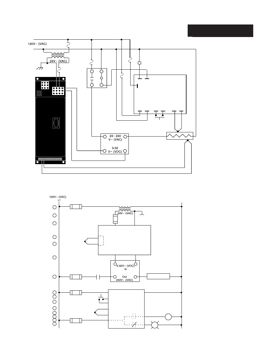
Figure 20 -
System Wiring
Example.
Figure 21 -
Series 733/734
Ladder Diagram
Example.
System Example
L1
L2
SSR-240-10G-DC1
TC
(+)
(-)
2
3
Process Sensor
Limit
Sensor
Coil
Normally Open
Momentary
Switch
142A-36XX-1200
UL recognized
safety limit control
(+)
(-)
Reset
L2
(+)
(-)
High Limit
Mechanical
Contactor
A001-0249-0001
6
9
3
2
73XX-1CA0-AXXX
NC
C
L1
NO
Over
Temp
Light
1
L2
2
2
3
7
8
1
2
1
2
(+)
(-)
3
14
21
15
16
17
18
2
1CR
19
Hi Temp. Light
1
2
3
4
8
9
10
11
12
13
14
R
TC (+)
TC (-)
N.O.
N.C.
SSR-240-10G-DC1
Reset
COM
COM
15
20
1
11
Heater
(+)
(-)
1 CR-1
12
13
2
3
2
9
10
6
9
6
5
4
5
6
7
L1
L2
A001-0249-0001
UL recognized
safety limit control
Series 733
73XX-1CA0-AXXX
Series 142
142A-36XX-1200
This manual is related to the following products: