Whirlpool 1997 "E" User Manual
Page 60
3-20
Ambient
Resistance
Temp. (˚F) Value
60
75.24 k
Ω (±11 kΩ)
68
62.57 k
Ω (±8 kΩ)
70
59.79 k
Ω (±8 kΩ)
80
45.80 k
Ω (±7 kΩ)
90
36.94 k
Ω (±6 kΩ)
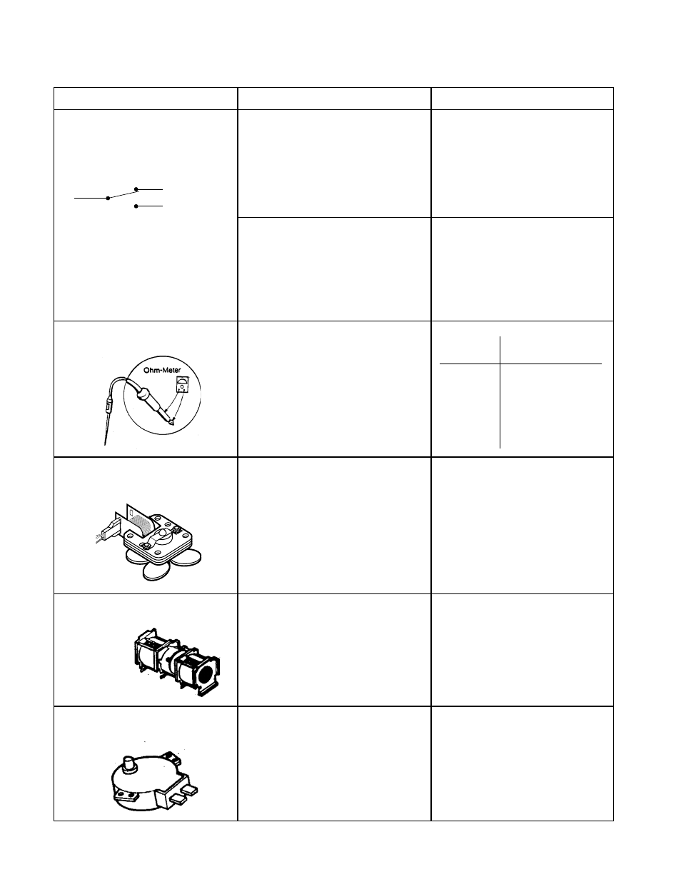
TEST PROCEDURE
RESULT
COMPONENT
N.O. and C Terminals
Set the ohmmeter to the
R x 1
scale, and measure the resistance
between the normally-open (N.O.)
and the common (C) terminals of
the switch.
Switches (with wire leads re-
moved). All of the switches are
measured in the same manner.
Temperature Probe
a) Fan Motor - Normal = 130
to 155 ohms.
Set the ohmmeter to the
R x 1
scale, and measure across the
terminals.
a) Normal - The meter indi-
cates infinity.
b) Abnormal - The meter
indicates zero ohms (a
short).
N.C. and C Terminals
Set the ohmmeter to the
R x 1
scale, and measure the resistance
b e t w e e n t h e n o r m a l l y - c l o s e d
(N.C.) and the common (C) termi-
nals of the switch.
b) Abnormal - The meter
indicates infinity.
a) Normal - The meter indi-
cates continuity, or zero
ohms.
Fan Motor (with leads discon-
nected).
Blower Motor (with leads dis-
connected)
Set the ohmmeter to the
R x 1
scale, and measure the:
a) High speed windings (blue
and black wires).
b) Low speed windings (blue
and white wires).
a) Normal - High speed: 25
to 45 ohms.
b) Normal - Low speed: 45
to 65 ohms.
C.
N.C. CONTACTS
N.O. CONTACTS
Set the ohmmeter to the
R x 1
scale, and measure the resistance
between the motor terminals.
Stirrer & Turntable Motors (with
leads disconnected)
a) Normal - 1 to 4 ohms.
b) Abnormal - Infinite or
zero ohms.
Set the ohmmeter to the
R x 10 k
scale, and measure the tempera-
ture probe with the leads posi-
tioned at either terminal.