Chapter 2. hardware installation, The front panel, The rear panel – TP-Link TL-WA5110G User Manual
Page 12: Chapter 2, Hardware installation, Front panel, Rear panel
4
Chapter 2. Hardware Installation
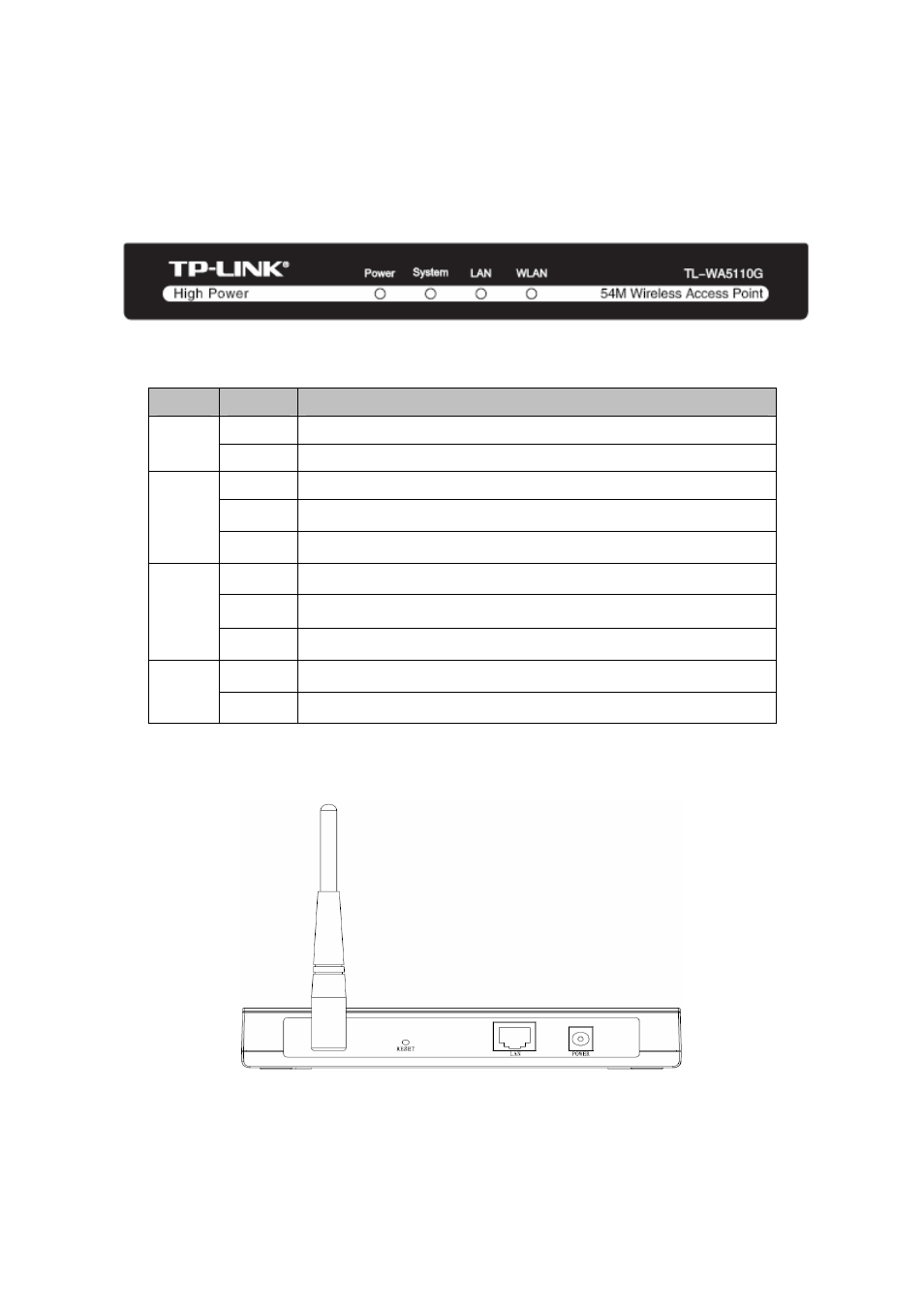
2.1. The Front Panel
The front panel of the TL-WA5110G consists of several LED indicators, which is designed to
indicate connections. View from left to right. Table 2-1 describes the LEDs on the front panel of
the router.
Figure 2-1 Front Panel sketch
LED Explanation:
Name
Status
Indication
Off No
Power
Power
On Power
on
Off
The AP has a hardware error
On
The AP is initialising
System
Flashing The AP is working properly
Off
There is no device linked to the corresponding port
On
There is a device linked to the corresponding port but no activity
LAN
Flashing There is an active device linked to the corresponding port
Off
The Wireless Radio function is disabled
WLAN
Flashing The Wireless Radio function is enabled
Table 2-1
2.2. The Rear Panel
Figure 2-2 Rear Panel sketch
¾
Wireless
antenna
¾
Factory Default Reset button
¾
There are three ways to reset the AP's factory defaults: