Toshiba CARRIER RAS-15LKV-UL User Manual
Page 64
– 64 –
10-7. OTHERS
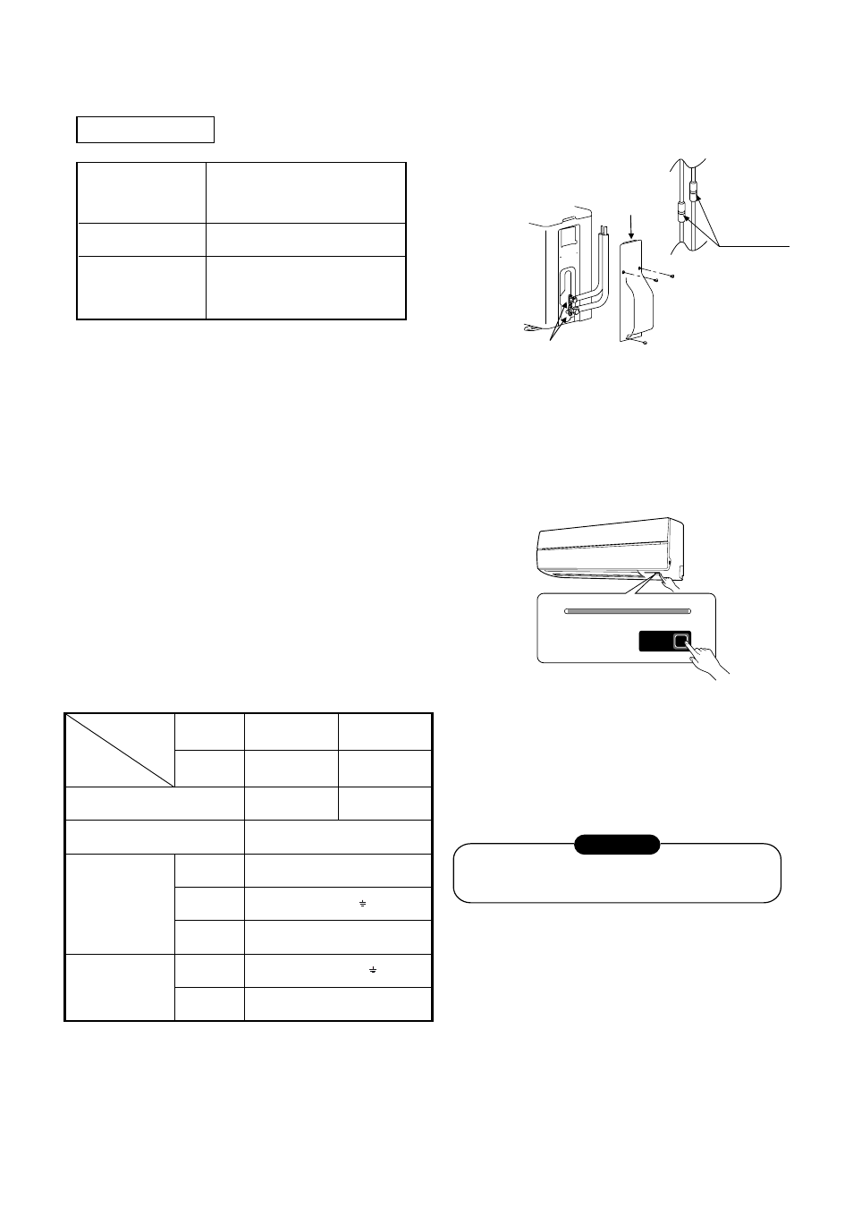
10-7-1. Gas Leak Test
Check the ß are nut
connections for the
gas leak with a gas
leak detector or
soap water.
Check places for
ß are nut connection
(indoor unit)
Check places for
the outdoor unit.
Valve cover
10-7-2. Test Operation
To switch the TEST RUN (COOL) mode, press RESET
button for 10 seconds. (The beeper will make a short
beep.)
Fig. 10-7-1
RESET
Hi POWER FILTER PAP TIMER OPERATION
RESET button
10-7-3. Auto Restart Setting
This product is designed so that, after a power failure,
it can restart automatically in the same operating mode
as before the power failure.
The product was shipped with Auto Restart function
in the on position. Turn it off as required.
Information
10-7-4. How to cancel the Auto Restart
1. Press and hold the RESET button on the indoor unit
for 3 seconds to cancel the operation. (3 beep sound
but OPERATION lamp does not blink)
2. Press and hold the RESET button on the indoor unit
for 3 seconds to set the operation. (3 beep sound and
OPERATION lamp blink 5 time/sec for 5 seconds)
· Do not operate ON timer and OFF timer3
Note : Default setting of auto restart operation is OK
Fig. 10-7-2
Refrigerant charge
Unit : ft (mm)
Refrigerant charge
Length of refrigerant Pipe
connected to Indoor/
outdoor unit
Additional refrigerant
6.6-50
(2-15m)
None
50-66
(15-20m)
Add 0.22oz/ft (20g/m) of
Refrigerant for piping that exceeds
50ft (15m) up to 66ft (20m)
* Caution during addition of refrigerant Max. amount of
additional refrigerant is 0.22 lbs (100g).
Charge the refrigerant accurately. Overcharging may
cause serious trouble with the compressor.
* Minimum refrigerant pipe is 6.6ft (2m).
Using pipe shorter than that may cause a malfunction of
the compressor or other devices.
•
The power supply shall be connected to the outdoor unit
by 3 wires.
•
The connecting cable between the indoor unit and outdoor
unit is 4 wires.
This cable provides the power for the indoor unit and the
communication signal between the outdoor unit and indoor
unit.
•
Consult local building codes, NEC (National Electrical Code)
or CEC (Canadian Electrical Code) for special requirements.
•
10-6-2. Power supply Connection and Connecting
Cable
FILE NO. SVM-10020
Product
Model
Item
Fuse / Circuit Breaker of main
power supply
Connect to
FCU/CDU
Power supply cord
(Not provide)
Inter connecting
cable between
FCU & CDU
(Not provide)
Size
4 (L1, L2, S, )
AWG14
No. of Core
Size AWG1
4
No. of Core
15A
CDU
3 (L1
, L2, )
RAS-22LKV-UL
RAS-22LAV-UL
Max. Current.
12.0A 13.5A
FCU
CDU
The following are the electrical requirements.
RAS-15LKV-UL
RAS-17LKV-UL
RAS-15LAV-UL
RAS-17LAV-UL