Texas Instruments 660 User Manual
Page 87
Troubleshooting Procedures
5-27
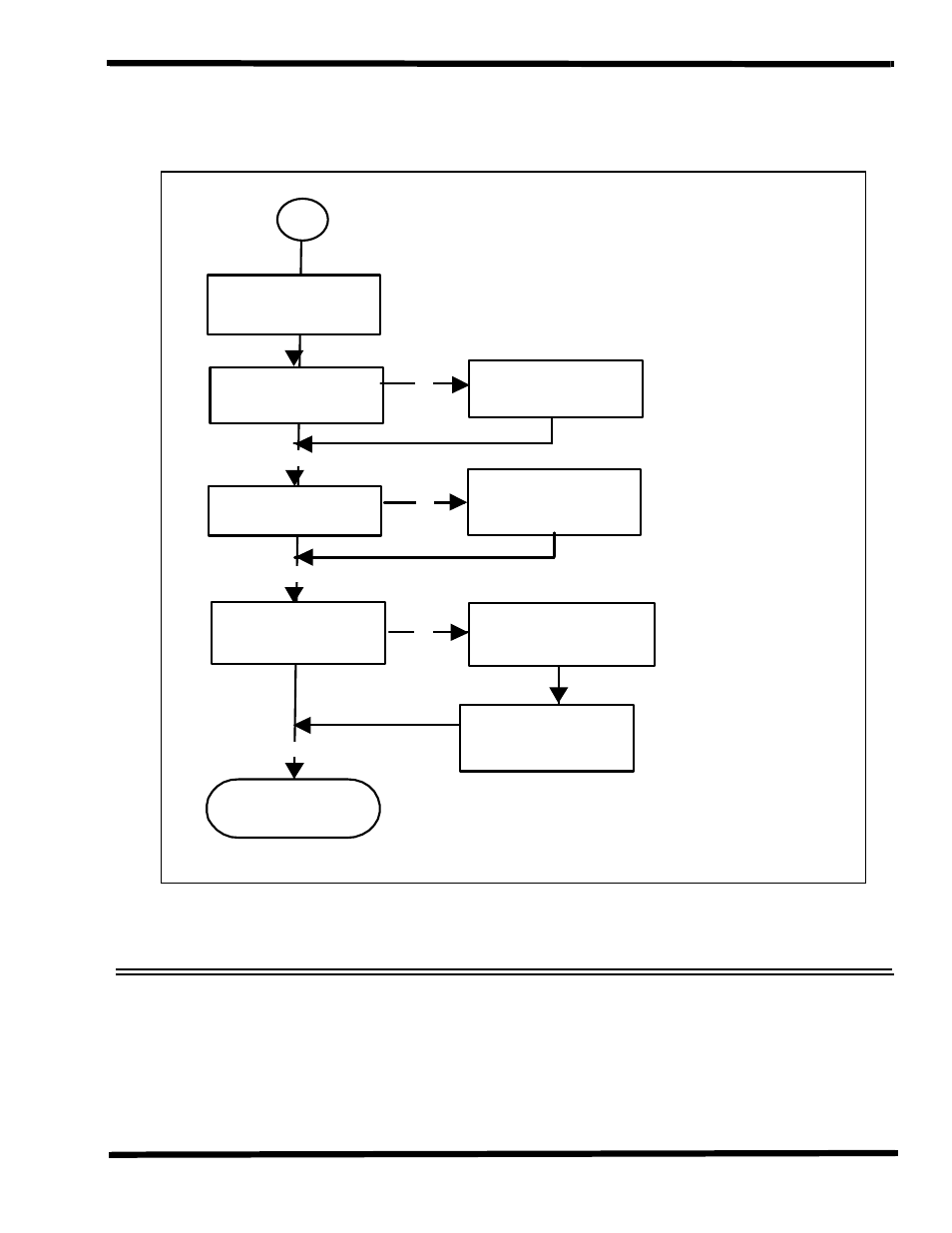
Figure 5-11 Battery Charger Interface Troubleshooting Diagram
System Fails to Boot:
Battery Charger Interface Checks
DC_IN=19V
Check F1, T3
U4=5V
Check D18
Charge Battery 1 or
Charge Battery 2
Check Charger Control
Board (RBC3) U1, D8,
D7
Check Battery Pack
Voltage & Temp
END
Yes
No
Yes
Yes
No
No
Plug-In AC Adapter
10