Removing/replacing the display assembly, 9 removing/replacing the display assembly – Texas Instruments 660 User Manual
Page 113
Field Service 6-19
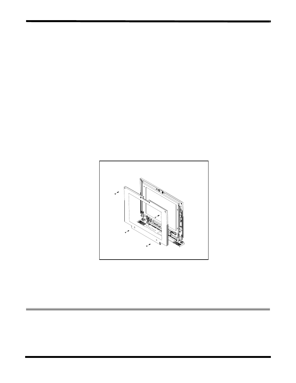
6.5.9 Removing/Replacing the Display Assembly
The procedure for removing and replacing the Display Assembly is as follows:
1.
Turn off the computer; disconnect the AC power adapter (if attached), and
remove the battery packs as described in Paragraphs 6.5.1 and 6.5.2.
2.
Press the Cover Release Latch and open the notebook to a full 180 degree
position.
3.
Remove four screws from the face of the LCD cover and pull the covers apart
starting at the top of the Display (refer to Figure 6-13).
4.
Remove the single screw holding the FPC Cable and gently remove the cable
connector (CN1) from the LCD Transfer Board.
5.
Remove five screws (3 on left hinge and 2 on the right hinge) and remove the
Cover-Display Assembly from the Base Assembly.
6.
Replacement is the reverse of Steps 1 through 5.
Figure 6-13 Removing/Replacing the Display Assembly