Introduction – Tripp Lite RACKMOUNT B020-U16-19-K User Manual
Page 5
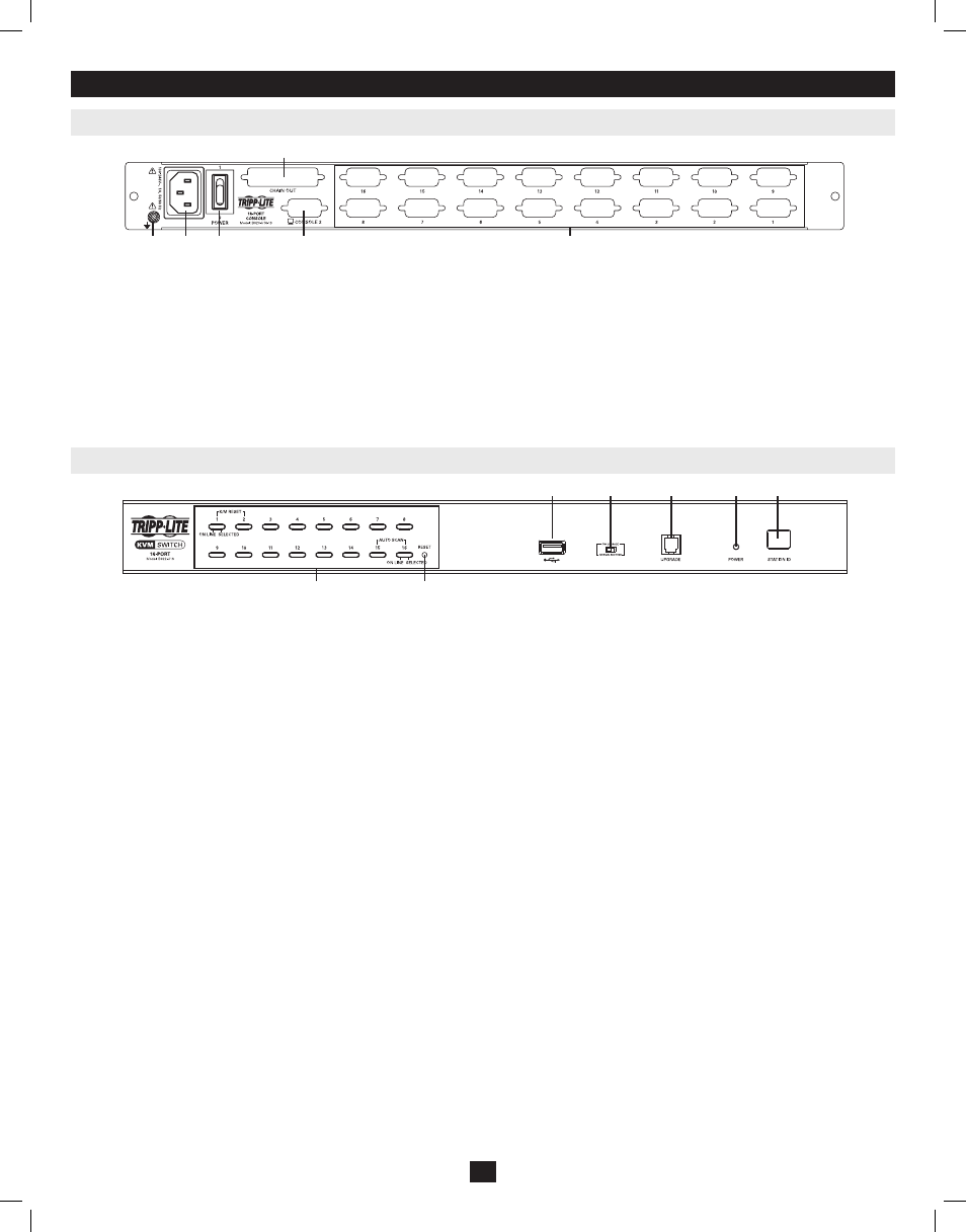
1. Port Push-Buttons/LEDs
There are 16 port selection push-buttons on the front panel, all of which
contain an LED.
• Press the push-button of any port to switch the KVM’s focus to that
port.
• An orange LED illuminates when a computer is connected to the
port and powered-on.
• A green LED illuminates when the computer connected to the port
has the KVM’s focus
• Pressing push-buttons 1 and 2 simultaneously will perform a
keyboard and mouse reset.
• Pressing push-buttons 15 and 16 simultaneously will start an Auto
Scan (see page 12 for Auto Scan details).
2. Reset Switch
Pressing this switch performs a system reset. This switch is semi-
recessed and must be pushed with a thin object, such as the end of a
paper clip or a ballpoint pen. Lights turn on to indicate that the KVM is
powered up and ready to operate.
3. Station ID LED
The B022-U16’s Station ID is displayed here. If this is a Single Station
Installation (see page 8), or the first station on a daisy-chained
installation (see page 8), the unit has a Station ID of 01. On a daisy-
chained installation, the KVM auto-senses its position and displays the
Station ID that corresponds to its place in the chain (see Port ID
Numbering
, page 11 for details).
4. USB Peripheral Port
A USB 1.1 port is provided for the sharing of USB peripherals among
connected computers (e.g. flash drive, CD-ROM drive, etc).
5. Firmware Upgrade Recovery Switch
During normal operation and while performing a firmware upgrade,
this switch should be in the NORMAL position. In the event of a
firmware upgrade failure, this switch is set to RECOVER to perform a
firmware upgrade recovery (see page 20 for firmware upgrade recovery
details).
6. Firmware Upgrade Port
The cable used to perform a firmware upgrade connects to the KVM
switch here.
7. Power LED
This LED illuminates when the KVM switch is powered ON.
3. Introduction
3.3 Front View of B022-U16
3.2 Rear View of Console KVM Switch
1. Daisy-Chain Port
When daisy chaining units, the cable plugs in here.
2. CPU Port Section
The cables that link to the computers plug in here.
3. Power Socket
This is a standard 3-prong AC power socket. The power cord from an
AC source plugs in here.
4. Power Switch
This is a standard rocker switch that powers the unit ON and OFF.
5. External Console Port
This port allows for the optional connection of an external keyboard,
mouse and monitor. The included USB/PS2 Combo Console Cable Kit
connects to the KVM switch here. Either USB or PS/2 keyboards/mice
can be connected.
6. Grounding Terminal
The included grounding wire connects to the KVM switch here.
5
1
2
3
4
1
5
2
3
6
4
6
5
7
201011080 • 932900-EN.indd 5
11/29/2010 4:30:12 PM