Introduction – Tripp Lite RACKMOUNT B020-U16-19-K User Manual
Page 4
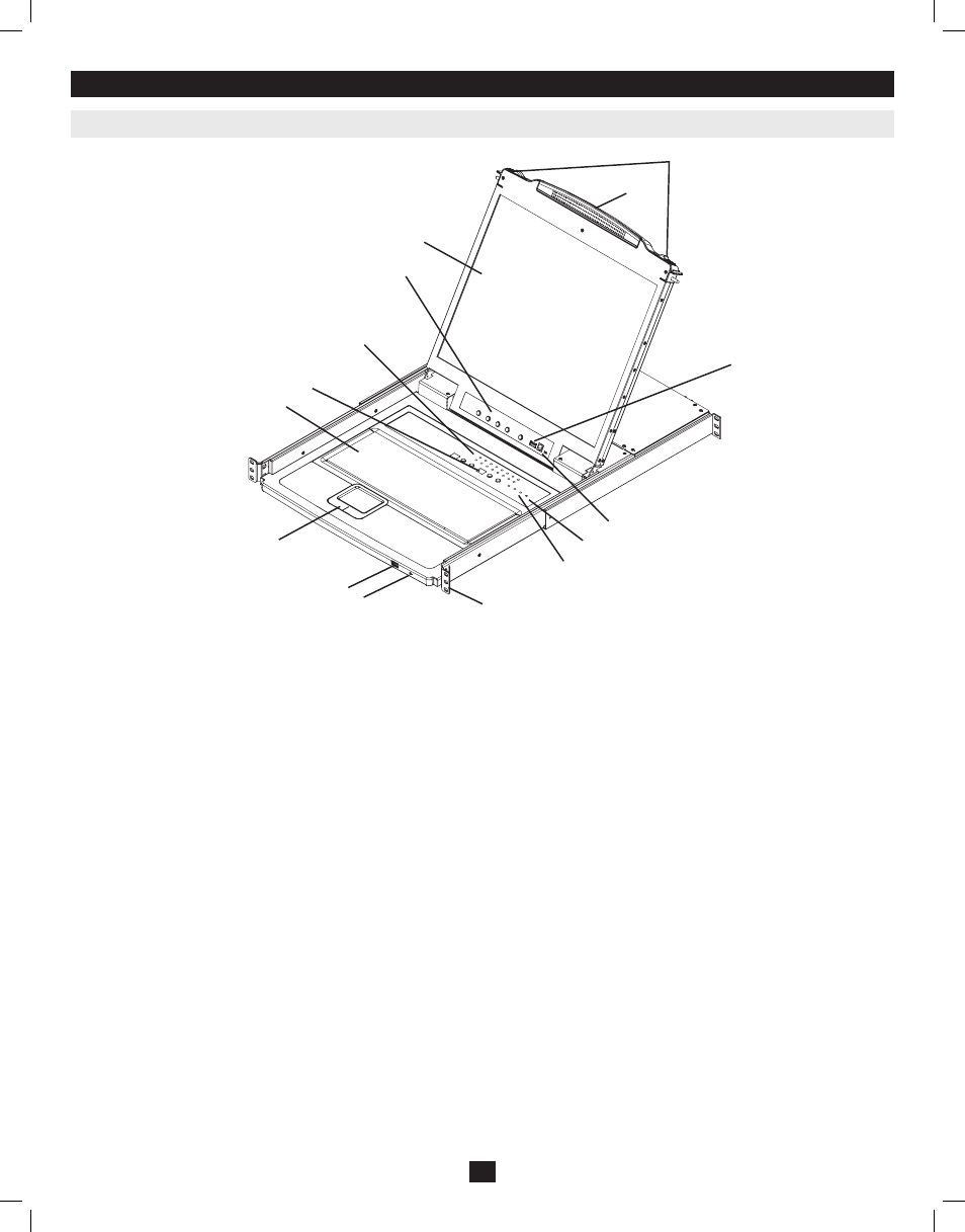
1. Handle
Pull to slide the KVM module out; push to slide the module in (see
item 13 in this table).
2. LCD Display
After sliding the KVM module out, flip up the cover to access the
LCD monitor.
3. LCD Controls
The LCD On/Off switch is located here, as well as buttons to control
the position and picture settings of the LCD display. See page 10 for
details.
4. Station/Port Switches
Press the Port ID up/down buttons to switch to the port before/after
the currently selected port. Press the Station ID up/down buttons to
switch to the station before/after the currently selected station.
5. LEDs
• Online Port LEDs – There are 8 or 16 LEDs (depending on the
number of ports) at the top of the key board panel which illuminate
orange when a computer is connected and powered-on.
• Port ID LED – A numerical LED displays the number of the port
which currently has the focus of the KVM switch.
• Station ID LED – A numerical LED displays the station number
of the KVM switch that currently has the focus of the console.
6. Keyboard
7. Touchpad
8. Power LED
Lights blue to indicate that the unit is receiving power.
9. Rackmounting Tabs
The rackmounting tabs located at each corner of the unit secure the
chassis to a system rack. Refer to page 7 for rackmounting details.
10. Lock LEDs
The Num Lock, Caps Lock, Scroll Lock LEDs are located here.
11. Reset Switch
Located to the right of the Lock LEDs. Press this recessed switch in
with a thin object to perform a system reset.
12. Firmware Upgrade Section
• Firmware Upgrade Port: The Firmware Upgrade Cable that
transfers the firmware upgrade data from the Administrator’s
computer to the Console KVM Switch plugs in here.
• Firmware Upgrade Switch: During normal operation this switch
should be in the NORMAL position. (See page 18 for firmware
upgrading details.)
13. Slide Release
In order to bring the console out, you must first release it by sliding
these tabs to the inside. See page 9 for details on sliding the console
in and out.
14. External Mouse Port
An additional USB port is provided on the front panel of the keyboard
module for an optional external mouse.
15. USB Peripheral Port
A USB 1.1 port is provided for the sharing of USB peripherals among
connected computers (e.g. flash drive, CD-ROM drive, etc).
3. Introduction
3.1 Front View of Console KVM Switch
4
13
15
11
12
10
9
1
2
3
4
5
8
14
7
6
201011080 • 932900-EN.indd 4
11/29/2010 4:30:11 PM