Basic operation – Tripp Lite RACKMOUNT B020-U16-19-K User Manual
Page 10
5.3 LCD OSD (On-Screen Display) Configuration
5.4 Sharing USB Peripheral Devices
5.5 Powering Off and Restarting
5. Basic Operation
The LCD OSD allows you to set up and configure the LCD display:
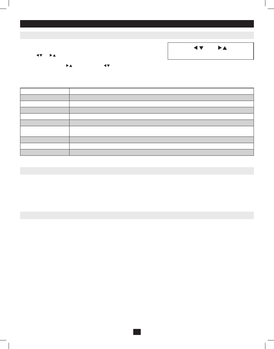
• To open up the LCD OSD main menu, press the button marked Menu.
• Use the | and | buttons to navigate and make adjustments. After navigating to a
setting choice, use the Menu button to bring up the adjustment screen.
• When making adjustments, | increases the value; | decreases the value.
• When satisfied, press Exit to return to the OSD main menu.
• When all adjustments have been made, press Exit to close the LCD OSD.
The following is an explanation of the settings:
Brightness
Adjusts the background black level of the screen image.
Contrast
Adjusts the foreground white level of the screen image.
Phase
Adjusts the vertical size of the screen image.
Clock
Adjusts the horizontal size of the screen image.
H-Position
Positions the display area on the LCD panel horizontally (moves the display area left or right).
V-Position
Positions the display area on the LCD panel vertically (moves the display area up or down).
Color Temperature
Adjusts the color quality of the display between three pre-configured settings; 6500k, 7500k, 9300k. This menu also
allows you to customize the individual RGB settings to your preference.
Language
Selects the language that the OSD displays its menus in.
OSD Duration
Adjust the length of inactivity before the OSD display turns off (between 5 and 100 minutes). The default is 5 minutes.
Reset
Resets all of the adjustments in the LCD OSD menus to their factory default settings.
Note: Pressing the Exit button while not in the LCD OSD Menu will perform an auto-configuration on the monitor.
The USB 1.1 port on the Console KVM Switch’s LCD panel and the B022-U16 front panel can be used to share USB peripherals between connected com-
puters. Simply connect a USB peripheral device to this port, and any connected computer you switch to will have access to the device.
Note: The following limitations apply to the USB peripheral port:
1. This port serves as a 1 port USB 1.1 hub; USB 2.0 devices will not function as designed.
2. USB peripherals can only be shared among computers that are connected to the KVM switch via the USB connectors on the P778-Series USB/PS2 Combo KVM Cable Kit.
3. USB peripherals can only be shared among computers that are connected to the KVM switch that the USB peripheral is plugged into. Computers that are connected to daisy-chained KVM
switches will not have access to the USB peripheral device.
If it becomes necessary to power OFF the KVM switch, follow the procedure below:
1. Shut down all computers connected to the KVM switch. If you are powering OFF a daisy-chain installation, shut down all computers connected to
each KVM switch in the installation. Note: It is necessary to unplug any computers that have the Keyboard Power ON function. If left on, the KVM
switch will continue to receive power via these computers.
2. Turn OFF the KVM switch (Console KVM only) and unplug the KVM switch from its power source. Power OFF and unplug each KVM switch in
the daisy-chain succession.
3. Wait 10 seconds and then plug the KVM switch, starting with the first station, back into its power source. Turn ON the power to the KVM switch
(Console KVM only).
4. Once the first station KVM switch has ascertained its position in the daisy-chain, power ON and plug in the next KVM switch in the installation.
Follow this procedure for each KVM switch in the installation.
5. Once all KVM switches in the installation have been powered back ON, turn on the power to all connected computers.
10
Exit
|
|
Menu
m
m
m
m
201011080 • 932900-EN.indd 10
11/29/2010 4:30:13 PM