Quantum Instruments Cascade Laser Starter Kit User Manual
Page 48
Starter Kit Instruction Manual
Maintenance
47
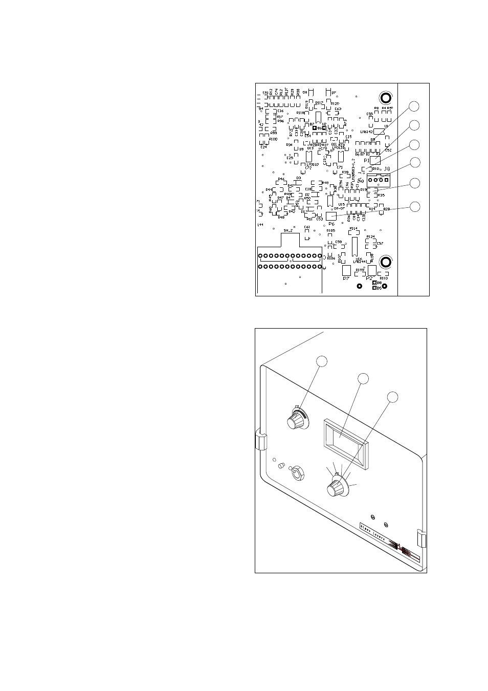
Sensing level and range adjustement
[4] Replace the cable connected to J8 (4) with
the 100Ω 1% reference resistor in the follow-
ing way:
Connect one side of the resistors to pins 1 and
2, the other side to pins 3 and 4.
[5] Measure the voltage on Zn3/R10 (3).
Note: The value should be:
- V = 1.22 to 1.25V.
[6] Measure the voltage at the intersection of
R19/R35 (5).
Note: The value should be: V=100mV (ad-
justable with the potentiometer P1 (2)).
Note: If the range is too small, replace the
resistor R1 (1) = 1.3kΩ with 1.4kΩ.
[7] Set the selector (9) to display Real
◦
C.
[8] Adjust the trimmer P6 (6) in order to ob-
tain the value of 000
◦
C on the screen (8).
[9] Vary the Temperature Reference by using
the Set Temperature 5 turns potentiometer
(7) located on the front panel.
Note: The range displayed should be -074 to
+ 074.
1
2
3
4
5
6
Fig.39: TCU151 main board
TCU151
Tem
pera
ture
Con
trolle
r
Alar
m
Res
et
Exte
rnal
Inte
rnal
Rea
l I
Rea
l C
Setti
ng
C
Setti
ng
+I
Setti
ng
−I
+
−
7
8
9
Fig.40: TCU151 front panel