Oki 6E User Manual
Page 55
3 - 7
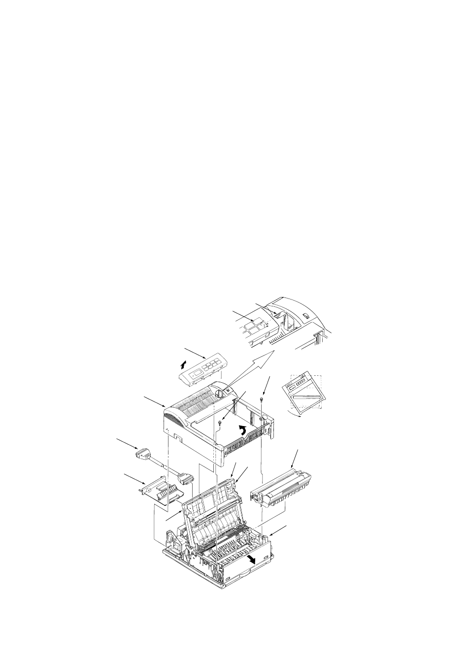
3.3.1
Upper Cover
(1) With the power switch turned off, unplug the AC power cord from the outlet.
(2) Disconnect the interface cable
1
.
(3) Remove the option board
D
if it is mounted.
(4) Lift the left side of the operator panel assy (or logo frame)
4
and remove it.
(5) Disconnect the flexible cable
5
from the connector (CN1)
6
of the operator panel PCB
6
,
and put the cable inside the cover. (OKIPAGE 6ex only)
(6) Open the stacker cover assy
9
by pressing the knobs
8
on the left and right sides.
(7) Remove the image drum unit
0
.
(8) Remove two screws
A
, and open the manual feed guide assy
B
. Lift the front of the upper
cover
C
up and release the claws at two locations on the back side. Align the stacker cover
9
against the diagonal line of the square holes of the upper cover and lift up the upper cover
C
slightly, then remove it.
Note: When removing or installing the upper cover, be careful not to damage the cable
5
.
5
6
4
C
A
A
1
D
8
9
8
=
B