Warning, 5 remote control wiring (option) – Omega RD260A User Manual
Page 21
2 - 9
2. INSTALLATION
2.2.5 Remote Control Wiring (option)
!
NOTE
The following settings are available only for the model with remote options (R1).
(1) Turn the power switch off.
(2) Remove the transparent cover of the optional terminals.
(3) Connect the wires for remote control to the optional terminals. The “C” is the
terminal common to other 1 to 5.
(4) Cover the terminals with the transparent cover and secure the screws.
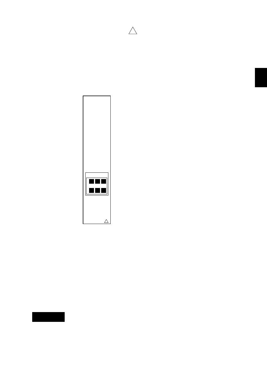
Remote control terminals are arranged as follows:
REMOTE
!
1
3
2
4
C
5
Remote Control Terminal Arrangements
Input characteristics:
Input signal
:
Dry contact, open-collector (TTL or transistor) signal
Control functions and signal types:
• Recording start/stop
level
• Chart speed change
level
• Printout messages
trigger more than 250 msec
Signal characteristics :
ON voltage
0.5 V or less (30 mA DC)
Leakage current in OFF state
0.25 mA or less
Signal duration
250 msec or more
Input types
:
Photocoupler isolation (one line common)
Internal isolated power source (5 V±5%)
Dielectric strength
:
500 V DC for one minute between input terminals and
grounding terminal.
To prevent an electric shock, ensure the main power switch is turned off before
wiring.
NOTE
• Use shielded cables for remote control signals to prevent noise pickup. The
shield should be grounded at the recorder’s terminal.
• To prevent an emission of electromagnetic disturbances, separate the remote
control wires from the power supply and input wires at least 0.1 m. Over 0.5
m is recommended.
WARNING