Figure 2-2 . ls-10i rear/bottom/top view, 2. ls-10i rear/bottom/top view, Pre l iminar y – Runco LIGHTSTYLE LS-10I User Manual
Page 23
Runco LS-10i Installation/Operation Manual
7
PRE
L
IMINAR
Y
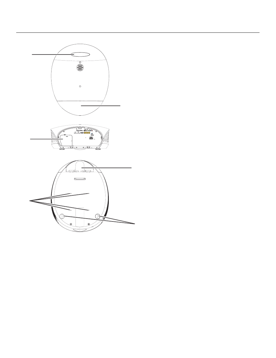
Figure 2-2. LS-10i Rear/Bottom/Top View
• RUNCO LOGO BADGE
• REAR COVER
Remove to access connectors.
• LAMP MODULE COVER
Remove this cover to access the lamp compartment.
• CABLE OPENING
Pass cables through this opening.
• CEILING MOUNT HOLES
Use these to attach the ceiling bracket to the projector. Use M4 screws with a
maximum screw depth of 10 mm (0.39 inch).
• ADJUSTABLE FEET
Use these when the projector is installed in a table-top configuration to level the image
and/or adjust the projection angle.
Runco Logo
Badge
Lamp Module
Cover
Ceiling Mount
Holes
Rear Cover
Cable
Opening
Adjustable
Feet